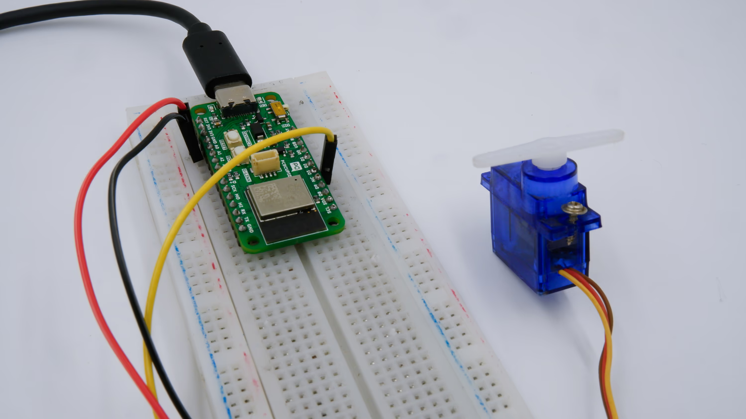
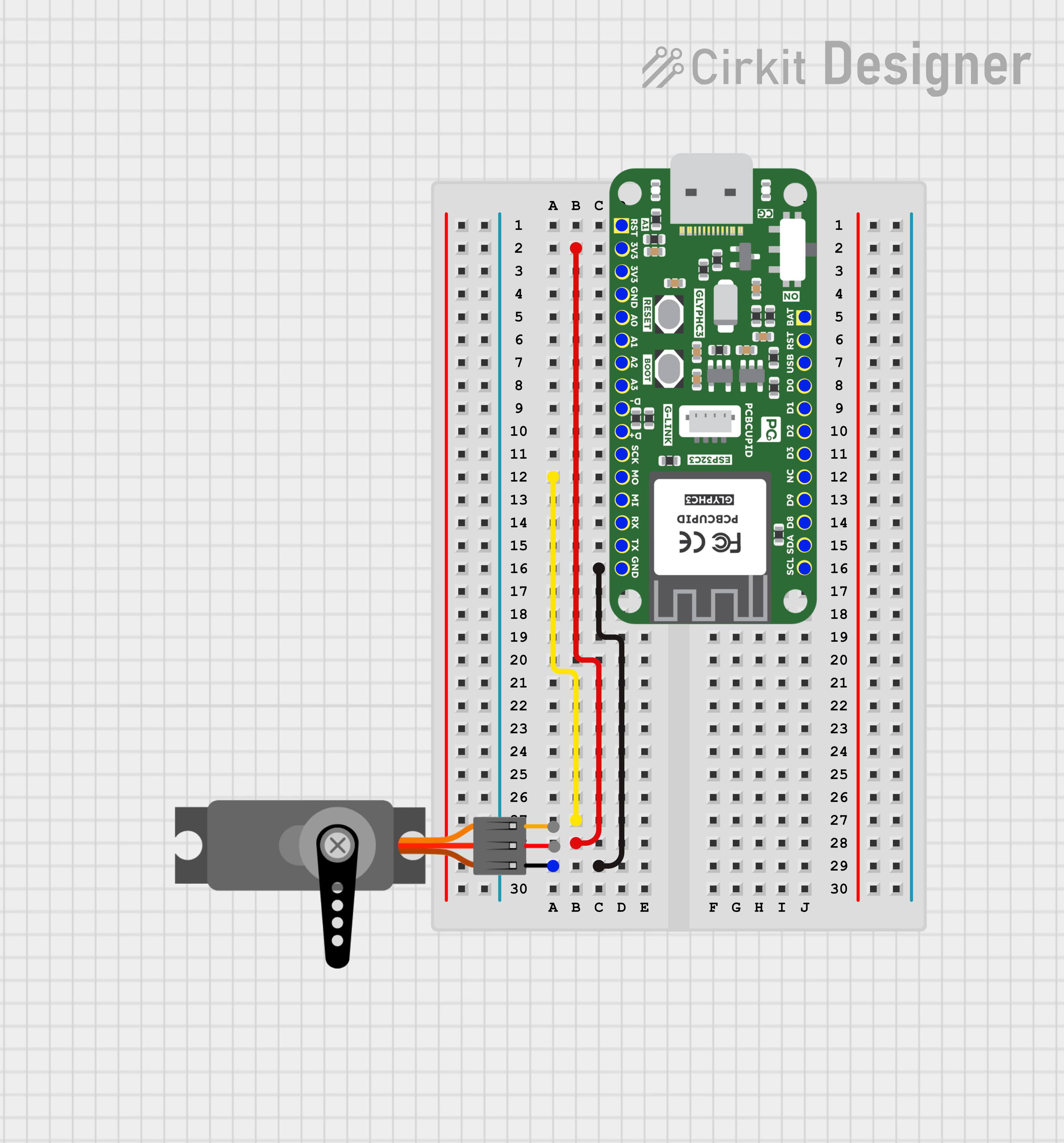
What is a Servo Motor and its Working PricipleA Servo Motor is a rotary or linear actuator designed for precise control of angular or linear position, velocity, and acceleration. It consists of a DC or AC motor, a position sensor (usually a potentiometer or encoder), and a control circuit.The motor’s position is controlled by varying the width of a Pulse Width Modulated (PWM) signal.A Servo Motor consists of a Motor (DC or AC), a potentiometer, gear assembly, and a controlling circuit. First of all, we use gear assembly to reduce RPM(Revolutions Per Minute) and to increase torque of the motor. Say at initial position of servo motor shaft, the position of the potentiometer knob is such that there is no electrical signal generated at the output port of the potentiometer. Now an electrical signal is given to another input terminal of the error detector amplifier. Now the difference between these two signals, one comes from the potentiometer and another comes from other sources, will be processed in a feedback mechanism and output will be provided in terms of error signal. This error signal acts as the input for motor and motor starts rotating. Now motor shaft is connected with the potentiometer and as the motor rotates so the potentiometer and it will generate a signal. So as the potentiometer’s angular position changes, its output feedback signal changes. After sometime the position of potentiometer reaches at a position that the output of potentiometer is same as external signal provided. At this condition, there will be no output signal from the amplifier to the motor input as there is no difference between external applied signal and the signal generated at potentiometer, and in this situation motor stops rotating.This guide will help you interface a Servo Motor with GLYPH-C6 board using PWM to control its angular position.Key Features of Servo Motors:
Closed-loop Control: Uses feedback from the position sensor to adjust movement for high accuracy.
High Torque & Precision: Can maintain a set position accurately.
Controlled via PWM: Typically controlled using a Pulse Width Modulation (PWM) signal in hobby applications.
Gearing System: Often includes a gearbox to reduce speed and increase torque.
Types of Servo Motors:
AC Servo Motors: Used in industrial automation, robotics, and CNC machines. High efficiency and accuracy.
DC Servo Motors: Common in robotics, RC cars, and consumer electronics. Cheaper but require more maintenance.
Stepper-based Servo Motors: Combine stepper motor principles with closed-loop feedback.
Linear Servo Motors: Provide linear motion rather than rotational.
Applications of Servo Motors:✅Robotics – Used for arm movement, humanoid robots, and industrial automation.
✅CNC Machines – Provide precise positioning for cutting, milling, and machining.
✅Drones & RC Vehicles – Control steering, flaps, and other movable parts.
✅Medical Equipment – Used in surgical robots and precision medical devices.
Install the Necessary Libraries
Open Arduino IDE and navigate to Sketch > Include Library > Manage Libraries. Search for ESP32Servo and install the library by Kevin Harrington.
Enter the following code into the Arduino IDE
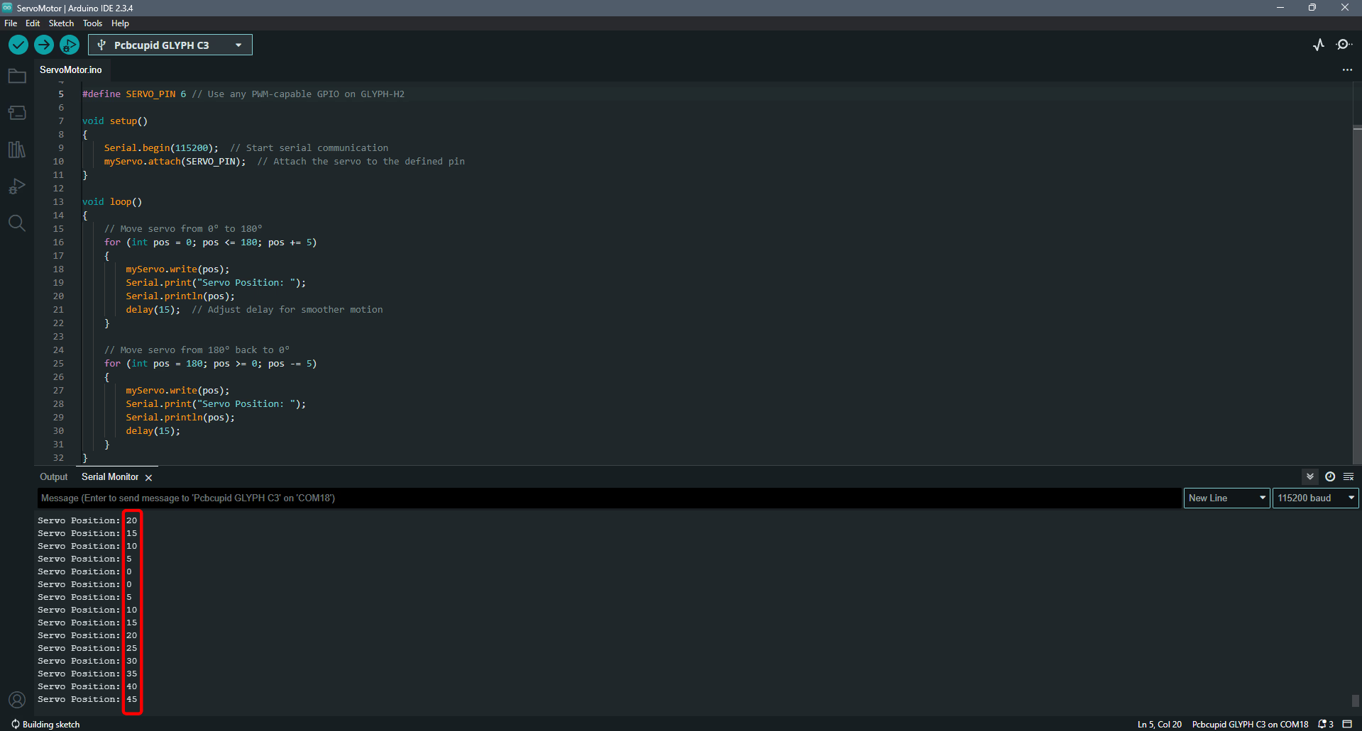
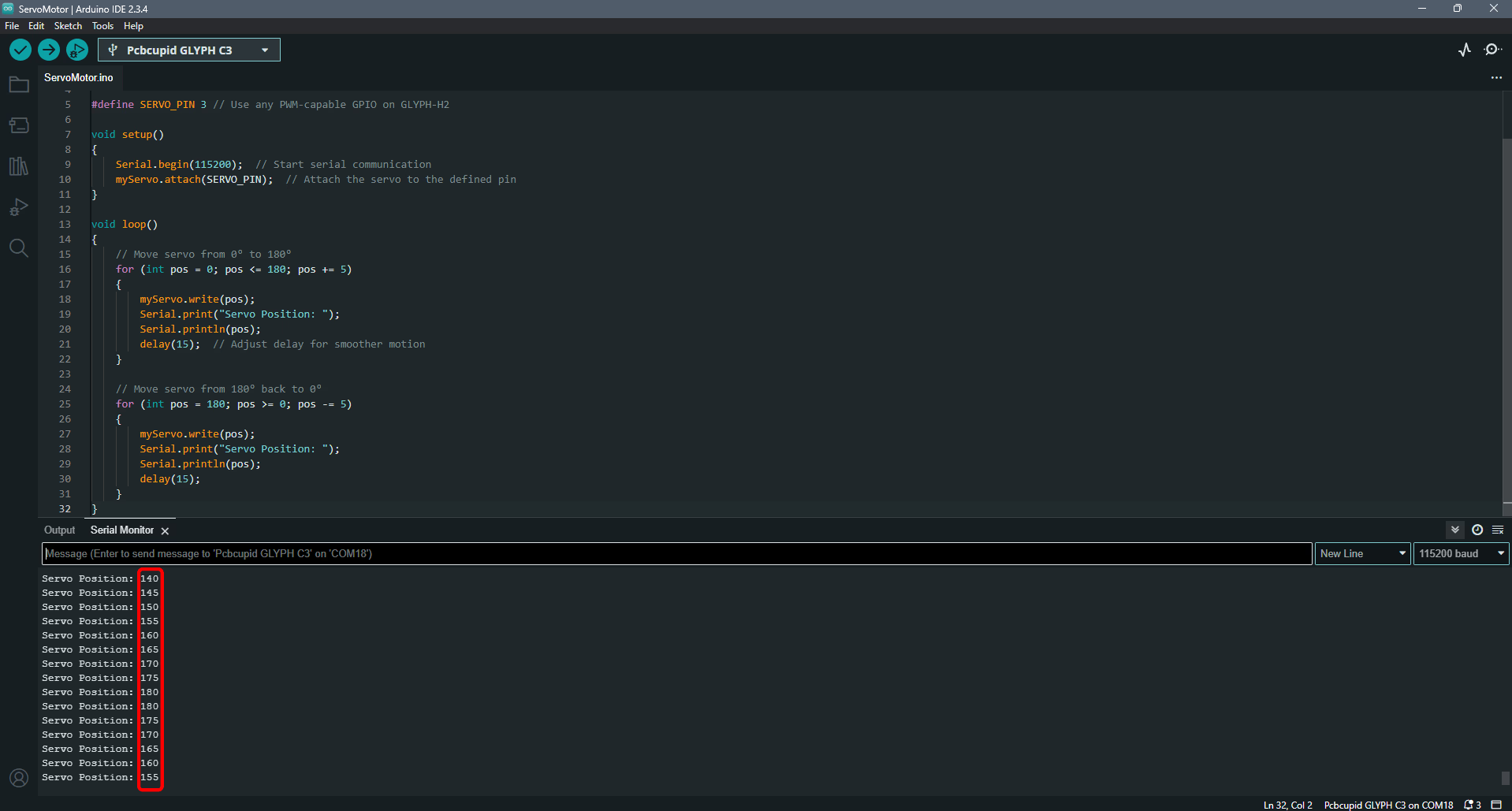
#include <ESP32Servo.h> // Include the ESP32 Servo libraryServo myServo; // Create a Servo object#define SERVO_PIN 6 // Use any PWM-capable GPIO on GLYPH-C6void setup() { Serial.begin(115200); // Start serial communication myServo.attach(SERVO_PIN); // Attach the servo to the defined pin}void loop() { // Move servo from 0° to 180° for (int pos = 0; pos <= 180; pos += 5) { myServo.write(pos); Serial.print("Servo Position: "); Serial.println(pos); delay(15); // Adjust delay for smoother motion } // Move servo from 180° back to 0° for (int pos = 180; pos >= 0; pos -= 5) { myServo.write(pos); Serial.print("Servo Position: "); Serial.println(pos); delay(15); }}
Select the Board and Port
Do the following settings in your Arduino IDE,
Do the following settings in your Arduino IDE,
Tools > Board > esp32 > Pcbcupid GLYPH C6
For the Pcbcupid GLYPH C6 to appear under Tools > Board > esp32, the esp32 board version installed in the Arduino IDE should be greater than or equal to 3.1.0.
Tools > Port and select the port connected to your GLYPH.
Tools > USB CDC on Boot >Enabled
If USB CDC on BOOT not enabled, you won’t be seeing any serial data on Arduino IDE.
Upload the Code
Click the upload button (➡️ icon) or use the shortcut CTRL + U in Arduino IDE to upload the code to the board.
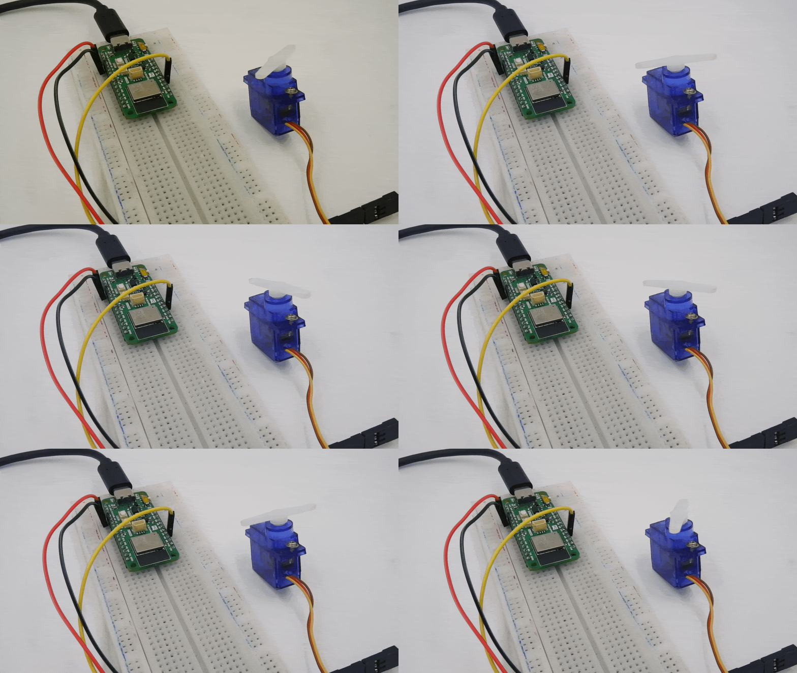
After uploading the code, open the Serial Monitor (Tools > Serial Monitor) and set the baud rate to 115200.You should see the servo motor moving back and forth from 0° to 180° and back, with the position being printed on the Serial Monitor.(If your servo does not move, check the wiring and ensure your power supply is sufficient for the servo’s requirements).