Touch Sensor (TTP223)
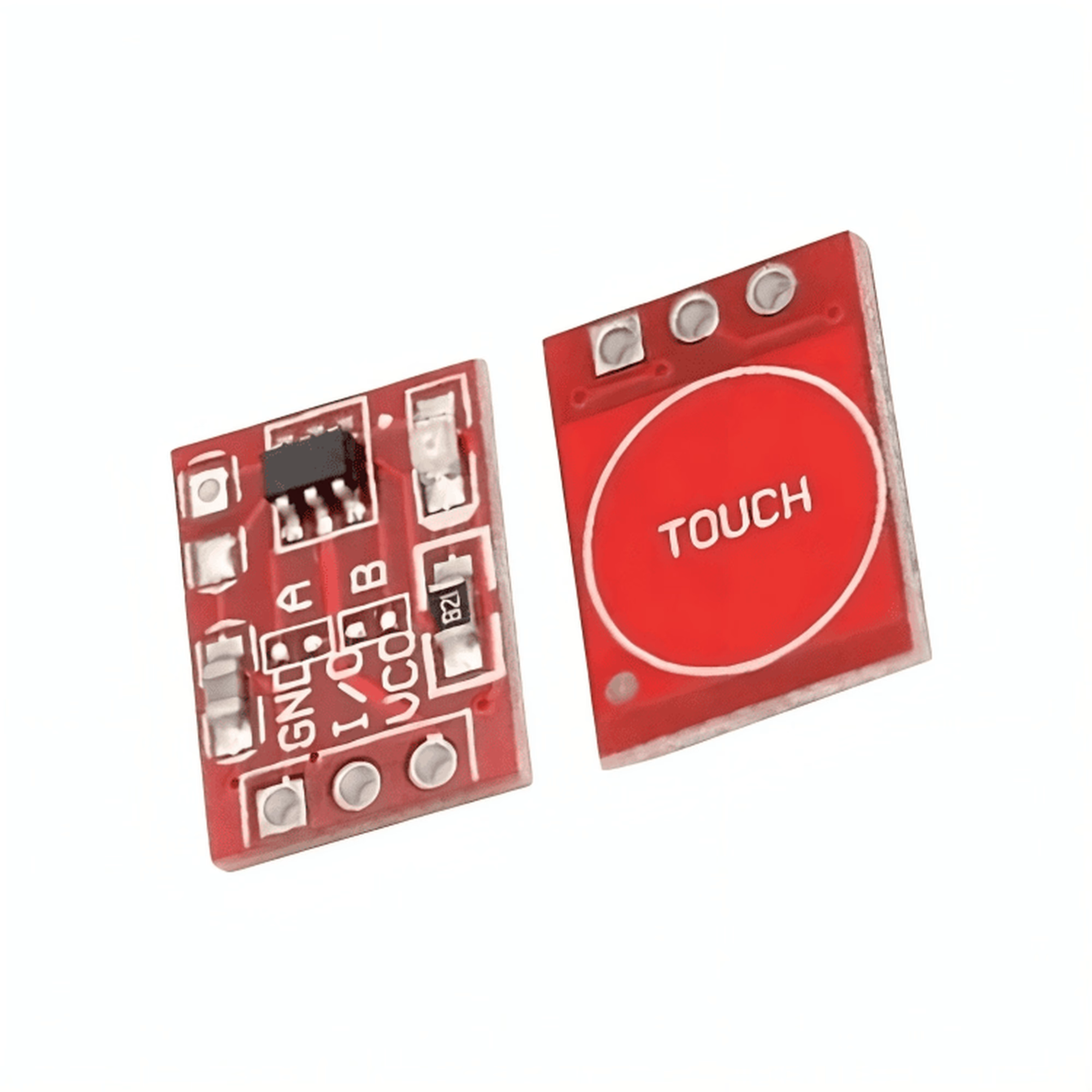
Overview
The TTP223 is a capacitive touch sensor module: touch the metal pad on the module and its output pin goes HIGH; release it and the pin goes back LOW. The pad detects your finger through the change in capacitance, so there are no mechanical parts to wear out — you can even hide the pad behind a thin sheet of glass or acrylic. The module is simple to use:- VCC — accepts 2 V to 5.5 V, so the board’s 3.3 V pin powers it directly
- GND — shared ground with the board
- OUT — digital output, HIGH while touched (momentary mode)
Pin Configuration
The TTP223 works from 2 V to 5.5 V, so the board’s 3.3 V rail is exactly right for it.
Some modules have an A/B jumper or solder pads that select the output mode: A = momentary (output HIGH only while touched — the default) and B = toggle (every touch flips the output and keeps it). This tutorial uses mode A, so make sure the jumper is on A if your module has one.
Key Features
- TTP223 capacitive sensing — no moving parts, nothing to wear out
- 2.0–5.5 V supply — runs directly from the GLYPH board’s 3.3 V pin, sips under 60 µA
- Digital output — HIGH while touched (momentary mode), plus an onboard touch LED
- Senses through thin insulators — glass, acrylic or paper up to a few millimetres
- Toggle mode option — the A/B jumper turns the module into a latching switch
Application
- Touch lamps and light switches
- Wake-up buttons for battery-powered devices
- Interactive controls and toy interfaces
- Replacing mechanical buttons in enclosures
- Hidden controls behind plastic panels
Step 1: Hardware Required
- Pcbcupid GLYPH-C6 board
- TTP223 capacitive touch module
- 3 × jumper wires (female–female)
- USB-C cable for power and upload
Step 2: Circuit Diagram
 Wire the module to the GLYPH-C6 as listed in Pin Configuration:
- VCC → the board’s 3V pin
- GND → the board’s GND
- OUT → GPIO 20
- If the module has an A/B jumper, make sure it is on A (momentary)
Step 3: Code Setup
Open the Arduino IDE and paste the sketch below into a new file. Every touch toggles the onboard LED and prints the event over Serial.Step 4: Upload the Code
- Connect the GLYPH-C6 to your computer with the USB-C cable.
- In the Arduino IDE, go to Tools → Board → esp32 → Pcbcupid GLYPH C6.
- Set Tools → USB CDC On Boot → Enabled.
- Select the board’s port under Tools → Port.
- Click the upload arrow button (or press Ctrl + U) and wait for the upload to finish.
Step 5: Observe the Output
Open the Serial Monitor at 115200 baud and touch the module’s pad:- The module’s own LED lights up while your finger is on the pad.
- The GLYPH-C6’s onboard LED toggles on and off with every tap.
- The Serial Monitor prints
Touched! (1),Released,Touched! (2), and so on.

Things to Try
- Touch through a cover — hold a sheet of paper or a piece of thin acrylic on the pad and touch that; the sensor still triggers.
- Hold and release — the output stays HIGH the whole time you hold the pad, which is why the “hold” behaviour is different from the “tap” behaviour.
- Go latching — if your module has an A/B jumper, move it to B and touch once: the module’s output now stays HIGH until the next touch, and the sketch only reacts on each state change.
Troubleshooting
- The board LED does not toggle — check the OUT → GPIO 20 wire, and that the module LED lights when touched.
- The LED toggles on its own — the pad can pick up interference from nearby mains wiring. Power the board from a USB power bank (battery) and see if the false triggers stop.
- The board LED is on when it should be off — your board’s LED may be active-low. Swap the
digitalWrite(LED_PIN, ...)HIGH/LOW values.