Overview
 This guide will walk you through configuring the GLYPH-C3 board to measure the voltage and charge percentage of a Li-ion or Li-Polymer(LiPo) battery. You will learn how to set up the board, connect the battery, and display the voltage readings on the Serial Monitor.
Voltage Measurement
Battery voltage measurement is the process of determining the electrical potential difference between the positive and negative terminals of a battery. It provides a quantitative value in volts (V), which indicates the charge level and health of the battery. The voltage range of a battery depends on its chemistry (Li-ion, LiPo, NiMH, Lead-Acid, etc.). The correct minimum (empty) and maximum (full) voltage values must be set to measure the charge percentage accurately. You need to update the Battery object with the correct min and max voltages.
Monitor Battery Health – Helps determine if the battery is functioning properly and whether it needs replacement. Prevent Overcharging & Deep Discharging – Ensures the battery is used within safe voltage limits to prolong its lifespan. Estimate Remaining Charge – Provides an approximate percentage of battery capacity remaining. Optimize Performance – Ensures the battery supplies the correct voltage for efficient device operation. Safety – Prevents excessive discharge or overvoltage conditions that may cause damage or overheating.
Step 1: Hardware Required
- Glyph Board
- Li-ion or Li-Polymer(LiPo) battery
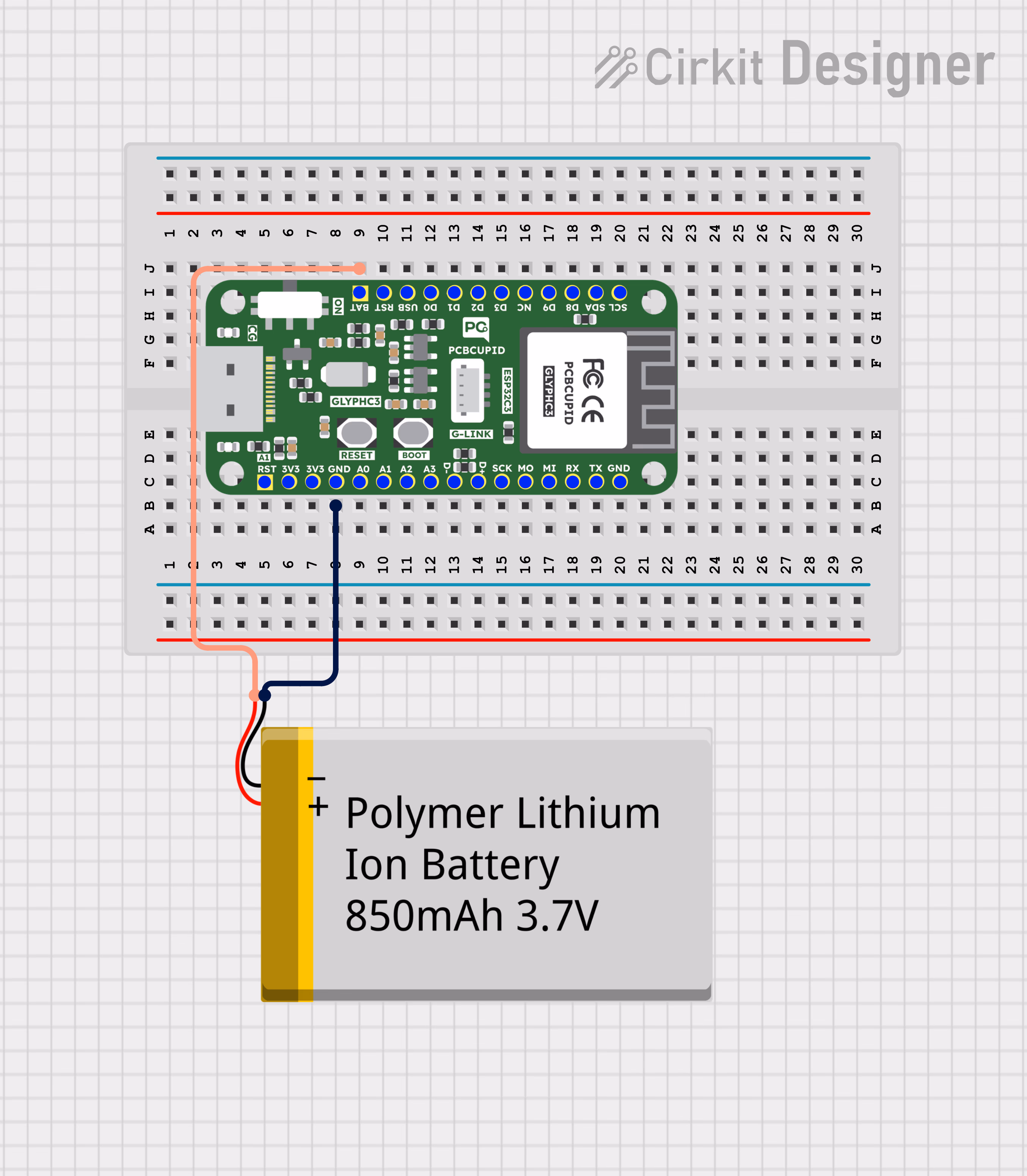
Step 2: Circuit Diagram
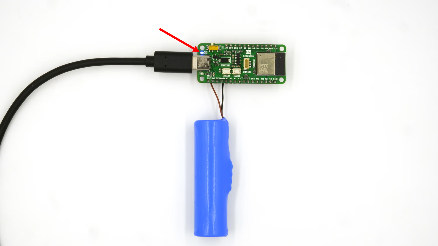
Circuit Diagram with Lithium Ion Battery:

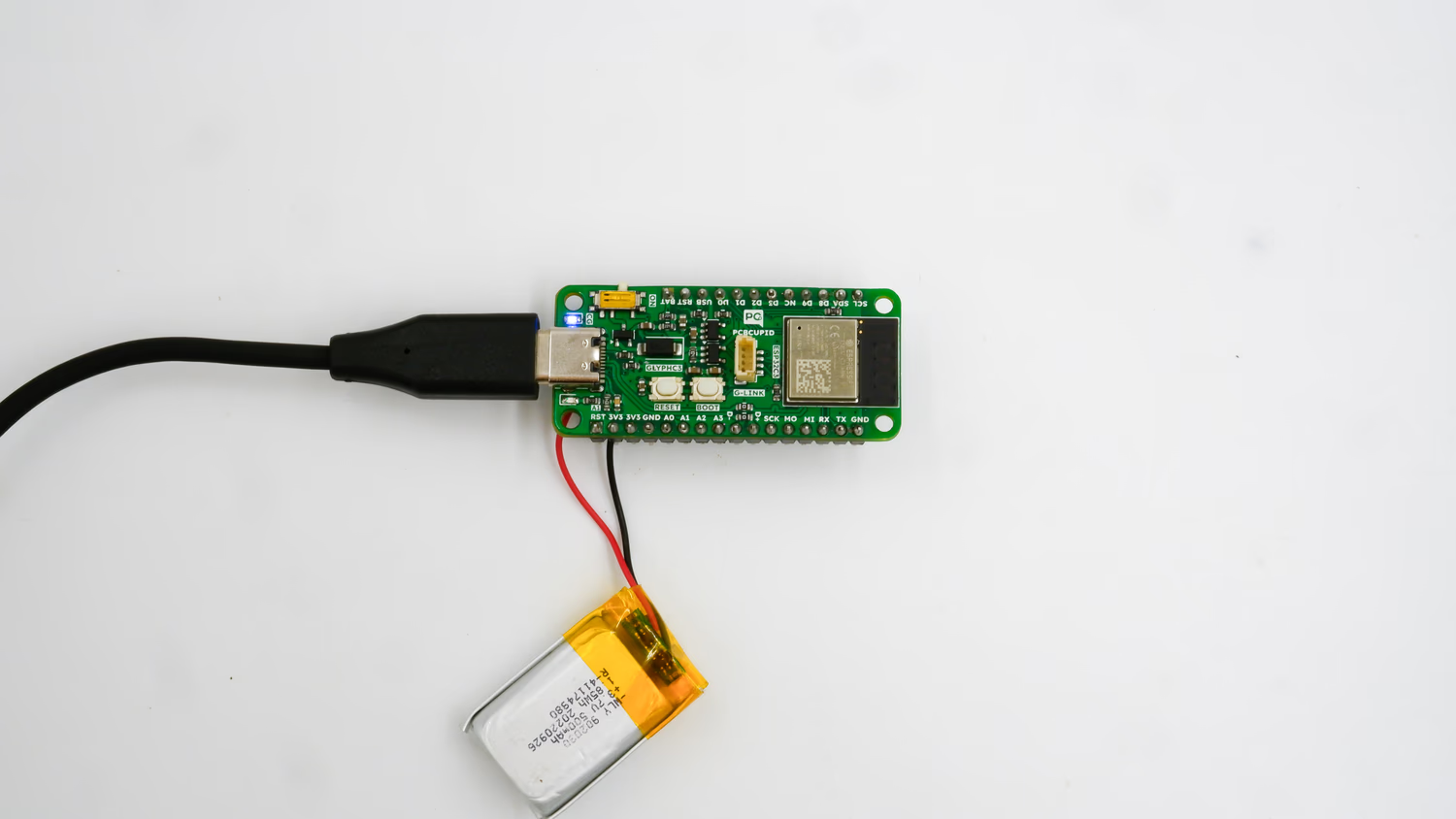
Circuit Diagram with Lithium Polymer Battery:
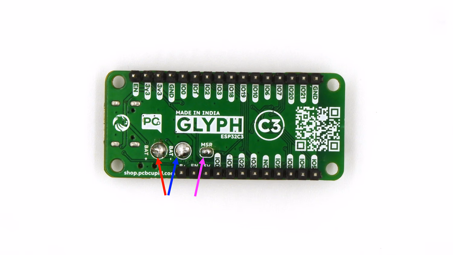
Step 3: Connect the Battery
- First Short the MSR Pin at the back of the Glyph C3 board
- Solder the Positive and Negative leads of the battery to the leads on the back of Glyph C3 which says BAT+ and BAT-
- Connect the positive terminal of the battery to the analog input pin on the board.
- Connect the negative terminal of the battery to the ground pin on the board.
Step 4: Code Setup
- Open Arduino IDE.
- Install the Battery Sense library by going to
Sketch > Include Library > Manage Libraries and searching for Battery Sense
- Copy and paste the following code into the Arduino IDE:
#include <Battery.h>

Battery battery(3400, 4200, A0,12); //(Battery voltage varies between 3.4V (empty) and 4.2V (full charge) in Li-ion/LiPo batteries.
//To convert raw ADC readings into actual battery percentage, the system needs a reference range (3400–4200 mV).
//The analog pin (A0) reads a voltage between 0V and 3.3V (scaled using a voltage divider).
//ADC resolution determines measurement accuracy (12-bit means values range from 0–4095).12 indicates the ADC Resolution bits for Glyph )
/**
 * 1 cell li-ion/li-poly battery wired to A0 before voltage booster, on demand sensing on pin 3, linear mapping function
 * https://github.com/rlogiacco/BatterySense#lesser-than-5v-with-voltage-booster
 **/

void setup()
{
	Serial.begin(115200);
	while (!Serial);
	battery.begin(3300,1.585); //(voltage divider A voltage divider is a simple electrical circuit that reduces a higher voltage to a lower voltage. It is commonly used in battery voltage measurement to ensure that the ESP32 (or any microcontroller) receives a safe voltage within its ADC (Analog-to-Digital Converter range).
//1.585 → Voltage Divider Ratio
//Since batteries typically output voltages higher than ESP32’s ADC limit (3.3V max), a voltage divider is used to scale it down.
//If your board has a different resistor divider, this value must be changed.
//How to Change for Different Batteries?
//If you have a higher voltage battery (e.g., 7.4V or 12V), you need:
//Larger R1 to drop more voltage.
//A new voltage divider ratio in the battery.begin() function.)
}

void loop()
{
   //Blinks the Onboard LED to indicate that the battery is connected and being measured.
	digitalWrite(1, HIGH);
	delay(500);
	digitalWrite(1, LOW);
	delay(500);

	Serial.print("Battery voltage is ");
	Serial.print(battery.voltage());
	Serial.print(" (");
	Serial.print(battery.level());
	Serial.println("%)");
}
ADC Calibration and Real-World Accuracy
One important thing to understand is that ESP32 ADC readings are not always perfectly accurate.
In real hardware, ADC readings can vary slightly due to:
- ADC non-linearity
- Resistor tolerances
- Board variations
- Noise
Because of this, a calibration factor is often used to fine tune the measured voltage.
Example:
const float CALIBRATION_FACTOR = 1.14;
Why Future Revisions May Use Dedicated Fuel Gauge ICs
While ADC-based battery measurement works well, it still depends on calibration and voltage estimation.
Future revisions of the GLYPH boards may use dedicated LiPo fuel gauge ICs over I2C for:
- Improved Accuracy
- Better Battery Estimation
- More Stable Readings
These dedicated chips are specifically designed for battery monitoring applications.
Here is the sample code with ADC Calibration
// ADC configuration
#define BATTERY_PIN A0
const float VOLTAGE_DIVIDER_RATIO = 2.0;       // 200k:200k divider
const float ADC_REF_VOLTAGE = 3.3;             // ESP32 ADC reference
const float CALIBRATION_FACTOR = 1.14;
const float MIN_VOLTAGE = 3.2;                 // Battery empty
const float MAX_VOLTAGE = 4.2;                 // Battery full

// Read battery voltage and A0
float readBatteryVoltage(int& rawADC, float& v_adc) {
  rawADC = analogRead(BATTERY_PIN);
  v_adc = (rawADC / 4095.0) * ADC_REF_VOLTAGE * CALIBRATION_FACTOR;
  float batteryVoltage = v_adc * VOLTAGE_DIVIDER_RATIO;
  return batteryVoltage;
}

// Map float
float mapFloat(float x, float in_min, float in_max, float out_min, float out_max) {
  return (x - in_min) * (out_max - out_min) / (in_max - in_min) + out_min;
}

// Battery percentage
int calculateBatteryPercentage(float voltage) {
  voltage = constrain(voltage, MIN_VOLTAGE, MAX_VOLTAGE);
  float percent = mapFloat(voltage, MIN_VOLTAGE, MAX_VOLTAGE, 0, 100);
  return (int)percent;
}

void setup() {
  Serial.begin(115200);
  analogReadResolution(12);           // 12-bit ADC
  analogSetAttenuation(ADC_11db);     // Full-scale input ~3.3V
  pinMode(BATTERY_PIN, INPUT);
}

void loop() {
  int rawADC;
  float v_adc;
  float batteryVoltage = readBatteryVoltage(rawADC, v_adc);
  int batteryPercent = calculateBatteryPercentage(batteryVoltage);

  Serial.println("=== Battery Monitor ===");
  Serial.printf("Raw ADC Value: %d\n", rawADC);
  Serial.printf("Voltage at A0: %.3f V\n", v_adc);
  Serial.printf("Battery Voltage: %.3f V\n", batteryVoltage);
  Serial.printf("Battery Percentage: %d%%\n", batteryPercent);
  Serial.println();

  delay(2000); // Update every 2 seconds
}
Step 5: Upload the Code
- Connect the Board
- Connect your GLYPH board to your computer
- Select the Board and Port Do the following settings in your Arduino IDE, Do the following settings in your Arduino IDE,
Tools > Board > esp32 > Pcbcupid GLYPH C3
For the Pcbcupid GLYPH C3 to appear under Tools > Board > esp32, the esp32 board version installed in the Arduino IDE should be greater than or equal to 3.1.0.
Tools > Port and select the port connected to your GLYPH.Tools > USB CDC on Boot > Enabled
If USB CDC on BOOT not enabled, you won’t be seeing any serial data on Arduino IDE.
- Upload the Code
- Click the upload button (➡️ icon) or use the shortcut
CTRL + U in Arduino IDE to upload the code to the board. Note: Ensure that the voltage applied to the analog pin does not exceed the maximum allowable voltage (usually 3.3V for the ESP32).
Step 6: Observe the Output
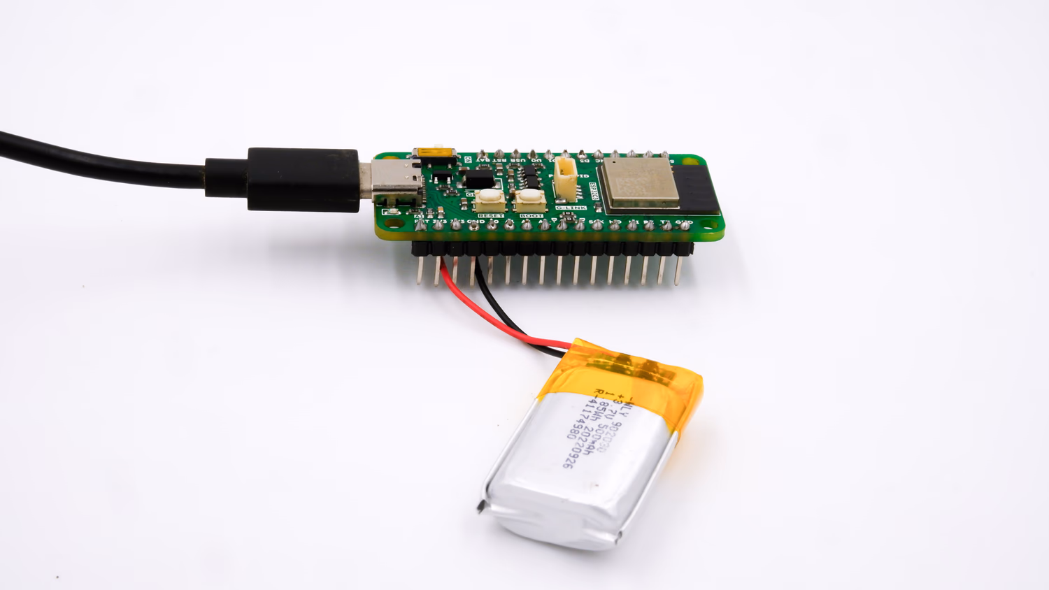
- See the LED Light up - After soldering the battery leads to the BAT+ & BAT- terminals and connecting your Glyph board to your PC, you can see the onboard led of your Glyph board light up like this:
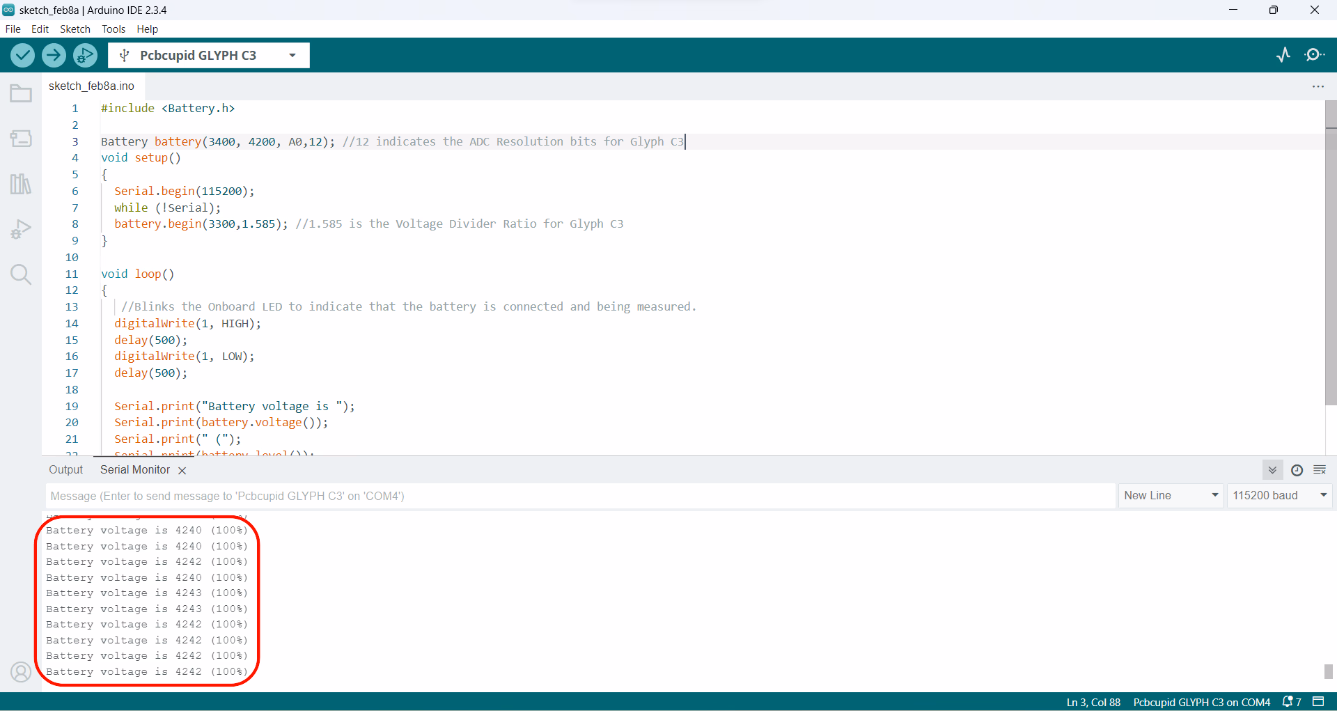
- Open Serial Monitor
- In Arduino IDE, go to
Tools > Serial Monitor or pressCtrl+Shift+M to open the Serial Monitor.
- View Battery Readings
- You should see the current battery voltage & battery charge percentage every second on the Serial Monitor.