Zigbee + GLYPH with Arduino IDE
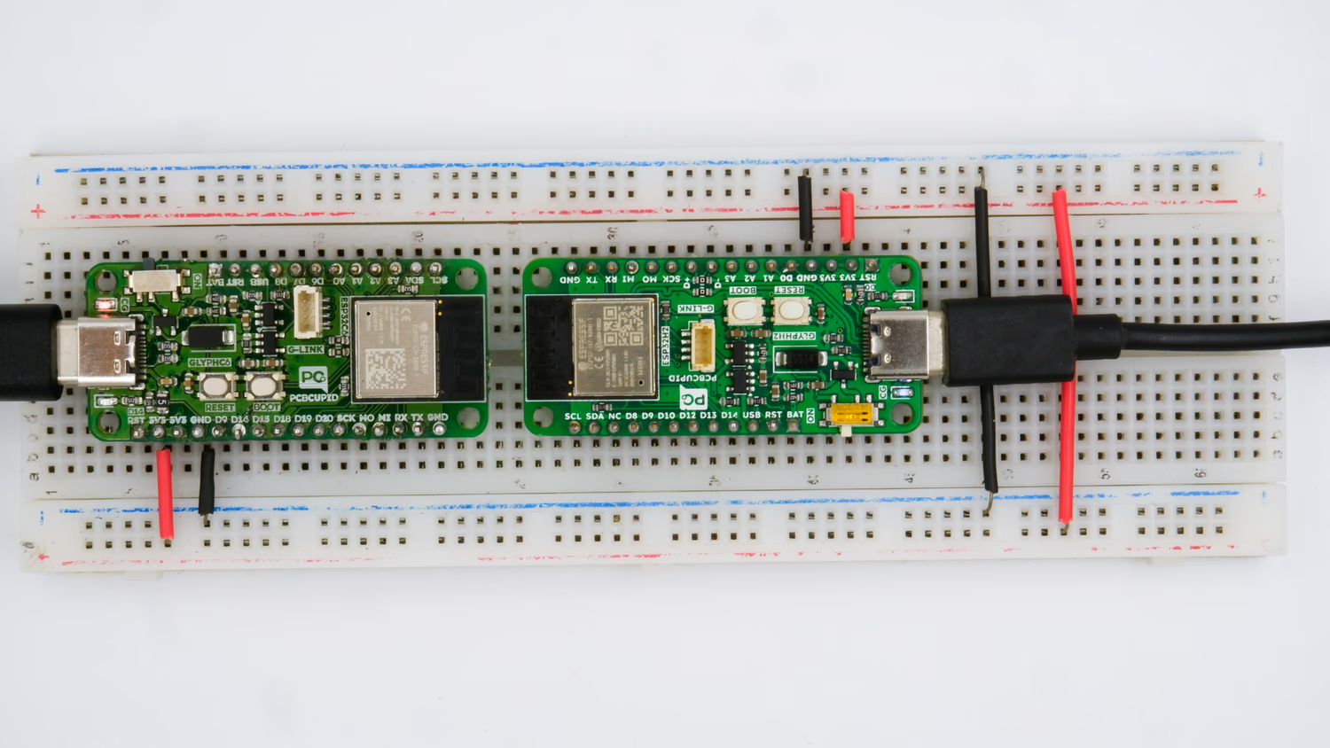
Step 1: Hardware Required
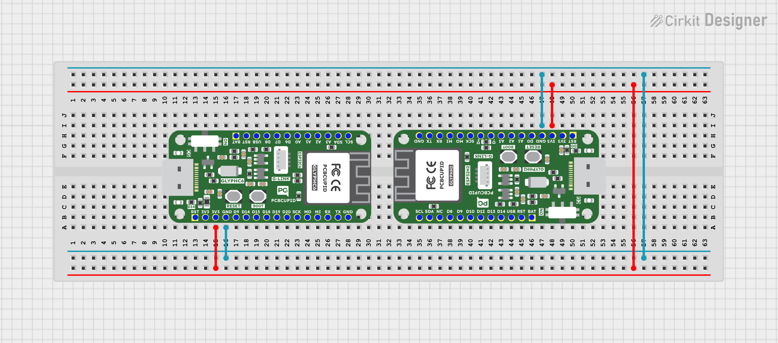
Step 2: Circuit Diagram
Step 3A: Prerequisites to achieve Zigbee communication
- Open Arduino IDE.
Recommended always download the latest version
- Go to File > Preferences.
- In the Additional Boards Manager URLs field, add:
https://espressif.github.io/arduino-esp32/package_esp32_index.json
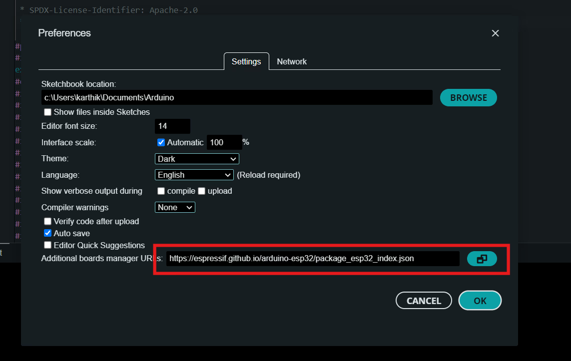
- ESP32 Board Definitions: Install ESP32 board support in the Arduino IDE.
- Go to Tools > Board > Boards Manager.
- Search for “ESP32” and install ESP32 by Espressif Systems and set it to the latest version
Step 3B: Setup Co-Ordinator
Plug-in your GLYPH development board, it can either be GLYPH C6 or GLYPH H2. We’ll setup any of this board as coordinator/router device. Thus, the coordinator device becomes the switch to control the LED on other device.- Now go to select other board and port > Pcbcupid Glyph C6 > Select your COM port.
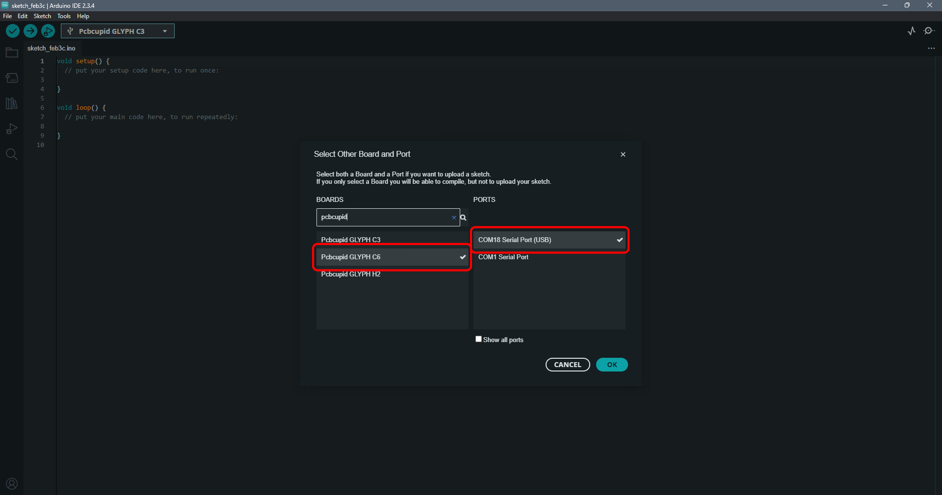
Now you can use the code below for the co-ordinator to act as a switch:
Configure Co-Ordinator
To configure the board, Go to Tools and set the following configuration keys in place.- Make sure the USB CDC On Boot is “Enabled”
- Set the Core Debug level to “Verbose”
- Set the flash size to “4MB (32Mb)”
- Make sure that the partition scheme is set to: “Zigbee ZCZR 4MB with spiffs”
- Set the Zigbee mode: “Zigbee ZCZR (coordinator/router)”
- Enable USB CDC on Boot: Activates USB serial communication on startup for easier debugging and setup.
- Set Core Debug Level to Verbose: Provides detailed log output to help troubleshoot issues during development.
- Set Flash Size to 4MB (32Mb): Ensures sufficient storage for firmware, Zigbee stack, and additional files.
- Set Partition Scheme to “Zigbee ZCZR 4MB with spiffs”: Allocates memory for both Zigbee network functionality and SPIFFS file storage.
- Set Zigbee Mode to “Zigbee ZCZR (coordinator/router)”: Configures the device as a coordinator/router for managing or extending a Zigbee network.
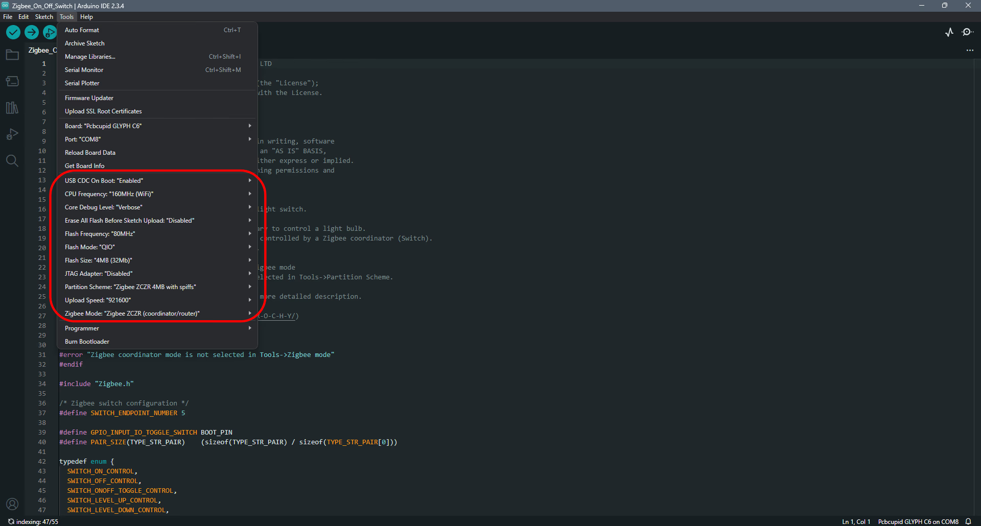
- Finally! compile, upload the code and start with programming the end-device.
Step 3C: Setup the end-device.
The end-device is the one that receives the signal from the coordinator and completes the action initiated by the coordinator it responds to. Thus, a Zigbee network can occupy up to 240 devices practically. These end devices form a connection with the coordinator through the same network ID, making communication possible. The communication can be unicast, multicast or broadcast. Plug in the GLYPH-H2 (GLYPH C6 can be used here as well) board. Here the GLYPH-H2 we’ll act as a end- device, which on receiving the signal from co-ordinator glows it’s in-built LED.- Now go to select other board and port > Pcbcupid Glyph H2 > Select your COM port.
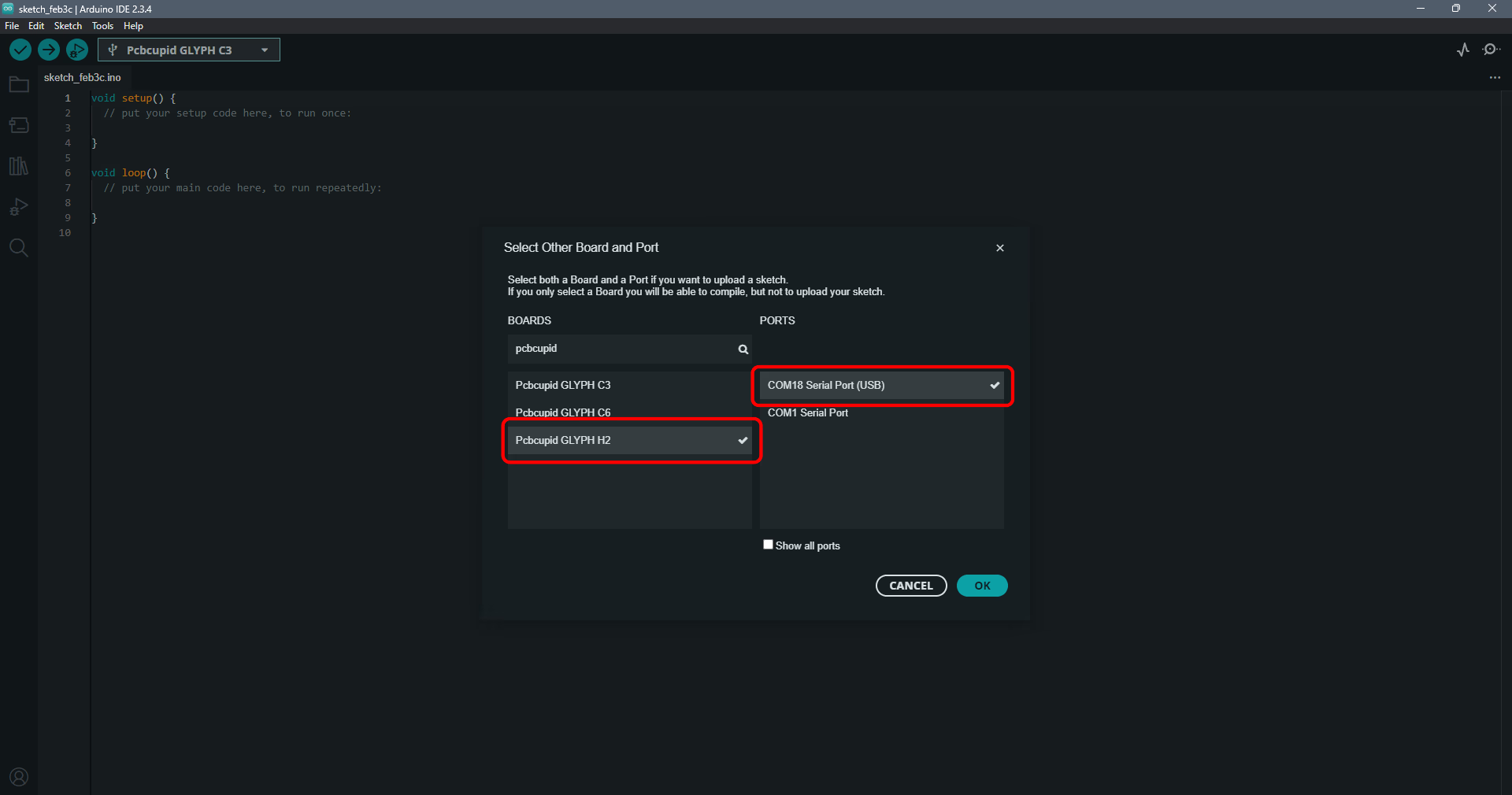
Configure end-device
- To configure the board, Go to Tools and set the following configuration keys in place.
- Make sure the USB CDC On Boot is “Enabled”
- Set the Core Debug level to “Verbose”
- Set the flash size to “4MB (32Mb)”
- Make sure that the partition scheme is set to: “Zigbee 4MB with spiffs”
- Set the Zigbee mode: “Zigbee ED (End device)”
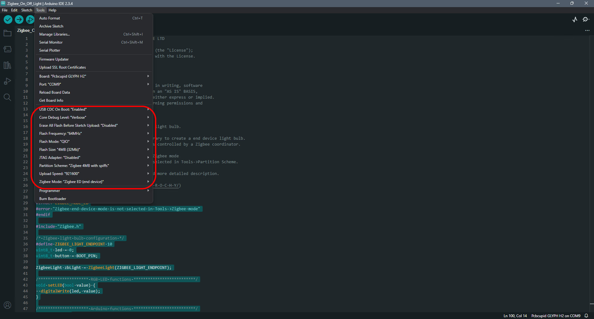
Now you can use the code below for the end-device to act as a light (controlled device):
- In the code “#define GPIO_INPUT_IO_TOGGLE_SWITCH 9” do not forget to add the GPIO pin that corresponds to the in-built LED/Button pin in GLYPH-H2/GLYPH-C6 or any other glyph board you connect.
- Always set the partition scheme relevant to the device you want to set it as - coordinator or end device.
If the device keeps continuously resetting, go to Tools> Erase all flash before sketch upload> Enabled. This will erase all the memory from the current board and gives a window of 180 seconds to reconfigure a new board to join the Zigbee network.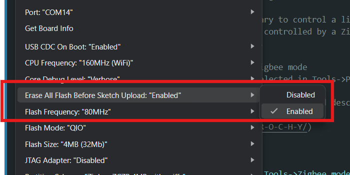
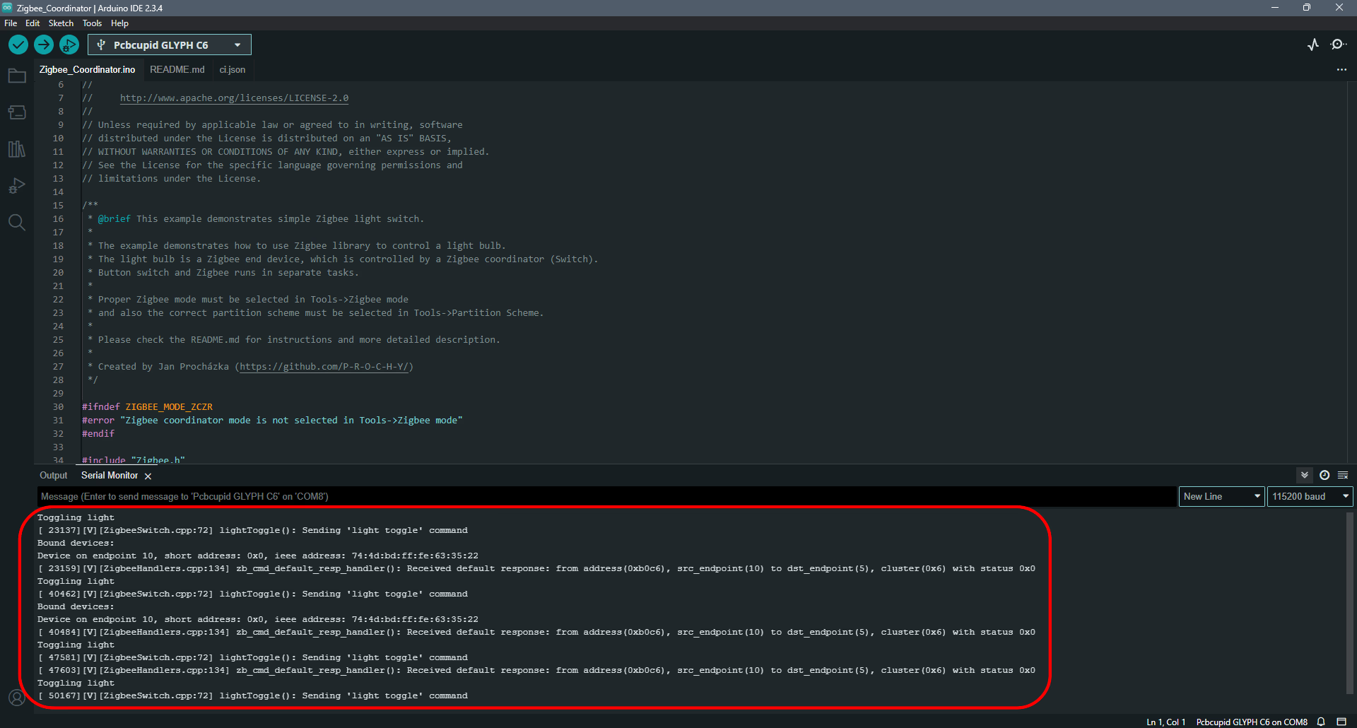
Step 4: Observe the Output on Serial Monitor
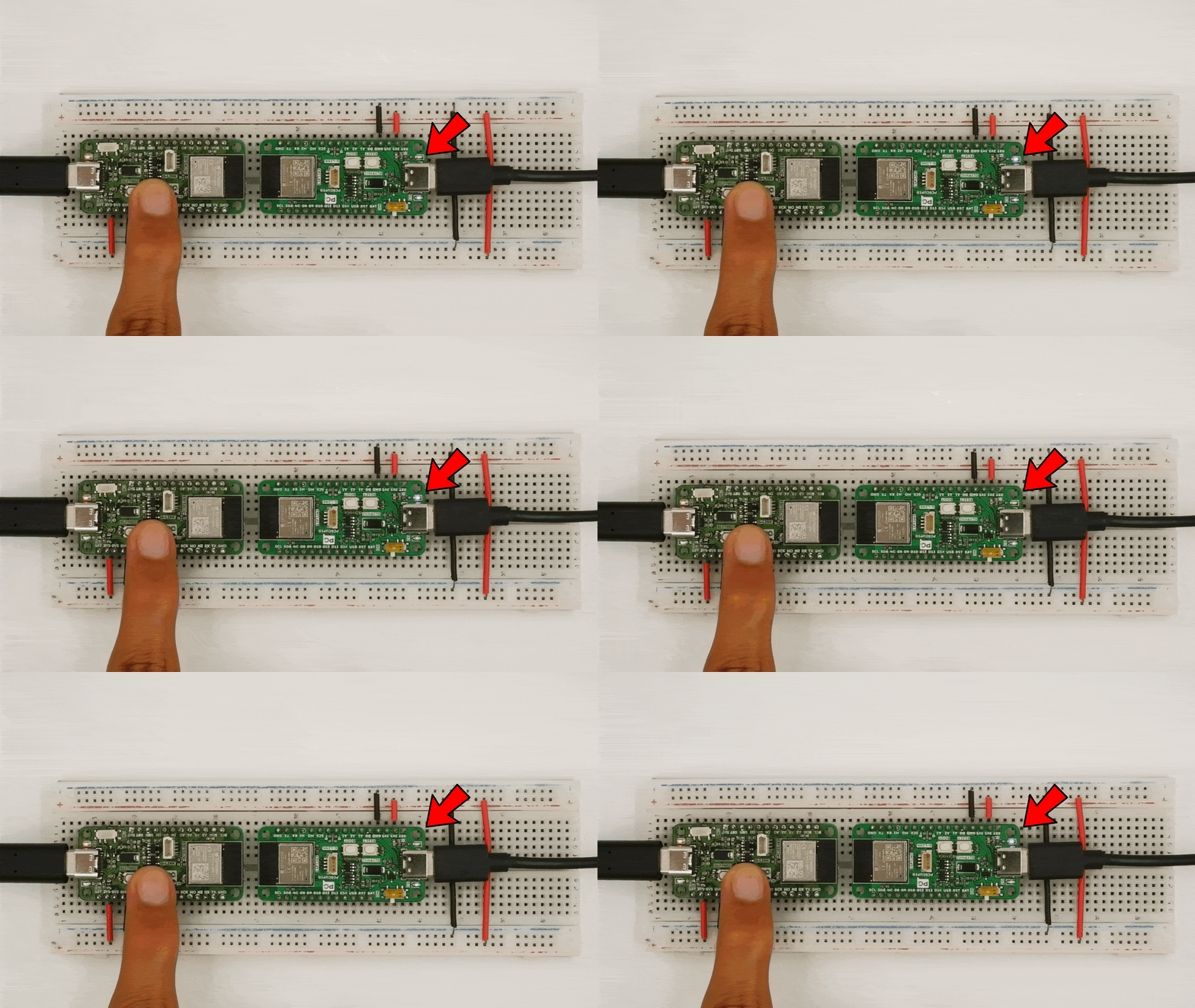
Open the serial monitor to observe the output along with the physical hardware: