LCD I2C
Introduction
The 16×2 LCD (Liquid Crystal Display) is a widely used alphanumeric display module capable of showing 16 characters per line on 2 lines. It is based on the Hitachi HD44780 controller, which provides a simple command-based interface for displaying characters, symbols, and custom graphics.
To reduce the number of GPIO pins required for communication, the LCD is often connected through an I²C I/O expander, typically the PCF8574 chip. This configuration allows the LCD to communicate with the microcontroller using only two wires — SDA (Serial Data) and SCL (Serial Clock) — instead of the usual 6 to 8 parallel data and control lines.
The PCF8574 acts as a bridge between the microcontroller’s I²C bus and the LCD’s parallel interface, providing:
- Pin saving
- Simpler wiring
- Easy software control
- Without it, you would need many more GPIO pins and complex wiring to operate the LCD.
Pin Configuration
| LCD Pin | Glyph-C3 |
|---|
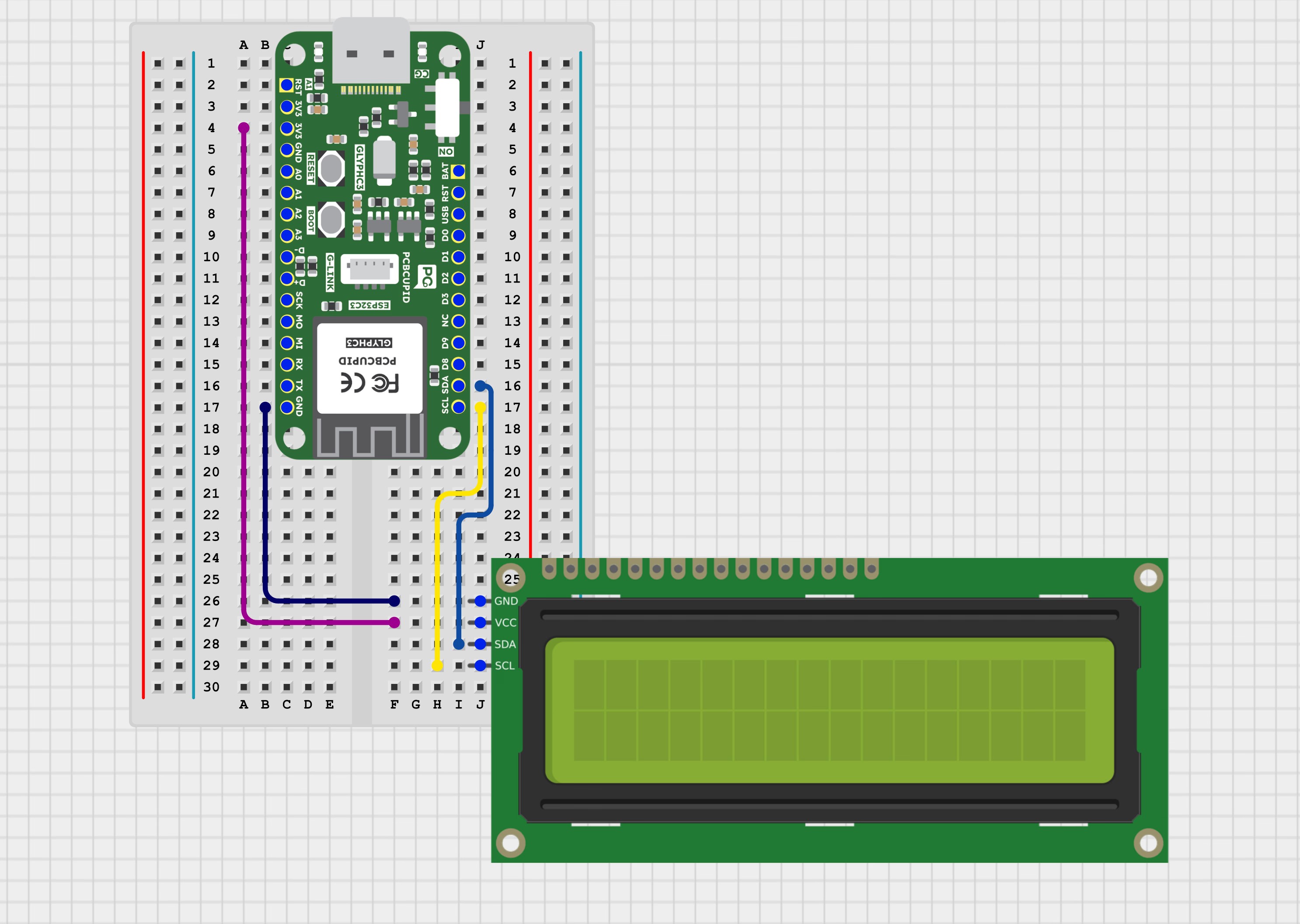
| VCC | Power Supply |
| GND | GND |
| SDA | GPIO 21 |
| SCL | GPIO 22 |
Features
- Uses I²C communication — only two wires (SDA and SCL) are required.
- Saves microcontroller pins — reduces pin usage from 8 (parallel) to 2.
- Compatible with the HD44780 LCD controller.
- Based on PCF8574 I/O expander for serial-to-parallel data conversion.
- Built-in LED backlight for better visibility.
- Adjustable contrast using the onboard potentiometer.
- Operates on 3.3V or 5V, suitable for most microcontrollers (Arduino, ESP32, ESP8266, Raspberry Pi).
- Displays 16 characters × 2 lines (total 32 characters).
Typical Applications
- Embedded system displays — show system status or information.
- Sensor data monitoring — display temperature, humidity, voltage, etc.
- Industrial control panels — parameter and status display.
- IoT devices — display device data or connection status.
- Educational and training projects — for learning I²C and LCD interfacing.
- Digital meters — voltage, current, and frequency measurement displays.
- Home automation systems — display time, mode, or device state.
Step 1: Hardware Required
- GLYPH
- LCD Display
- PCF-8574
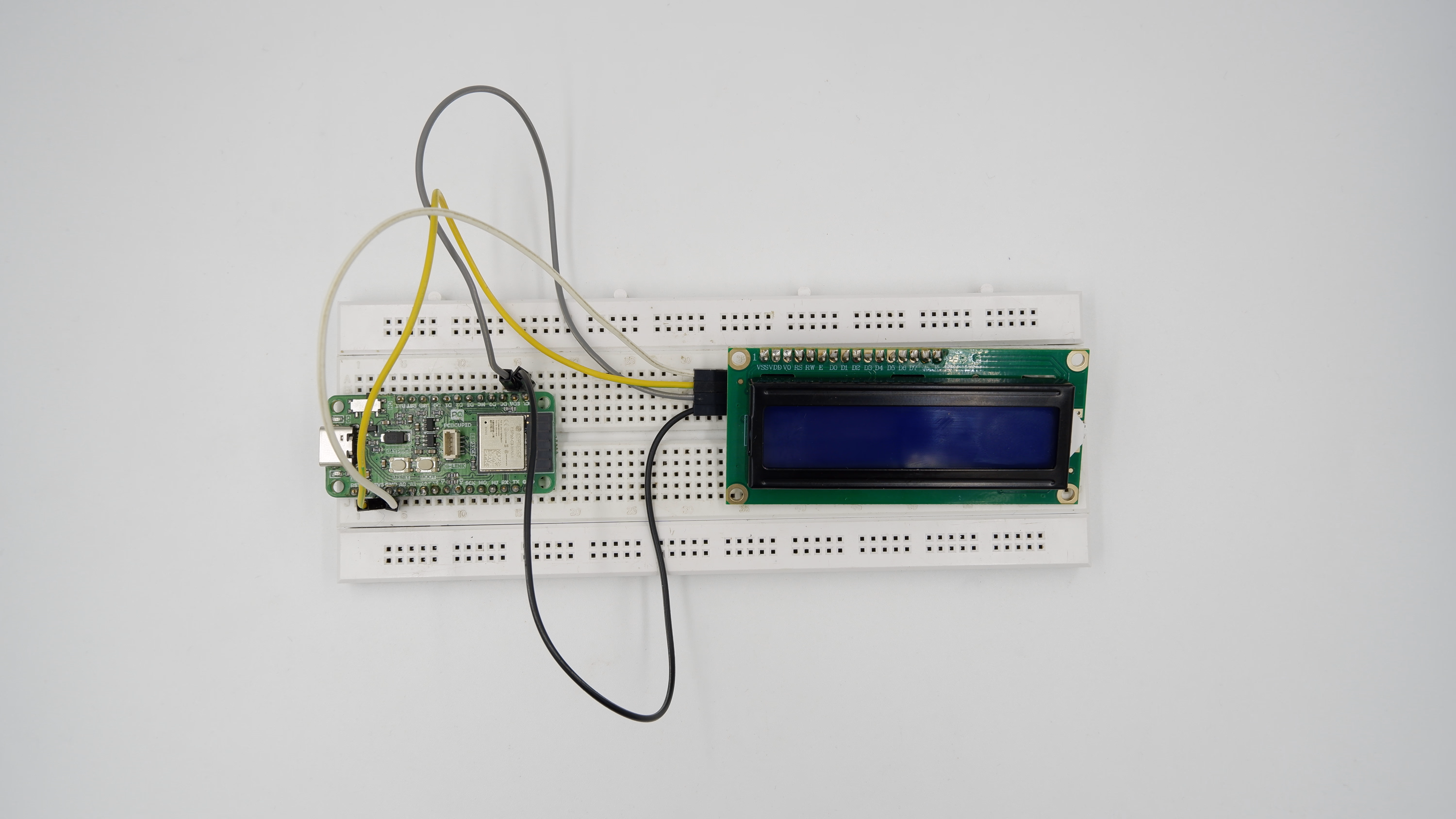
Step 2: Circuit Diagram
Step 3: Code Setup
- Open Arduino IDE.
- Make sure to install the library
- Copy and paste the following code into the Arduino IDE
#include <Wire.h>
#include <LiquidCrystal_I2C.h> // https://www.arduinolibraries.info/libraries/liquid-crystal-i2-c
// Initialize LCD: I2C address 0x27, 16 columns, 2 rows
LiquidCrystal_I2C lcd(0x27, 16, 2);
void setup() {
lcd.init(); // Initialize the LCD
lcd.backlight(); // Turn ON backlight
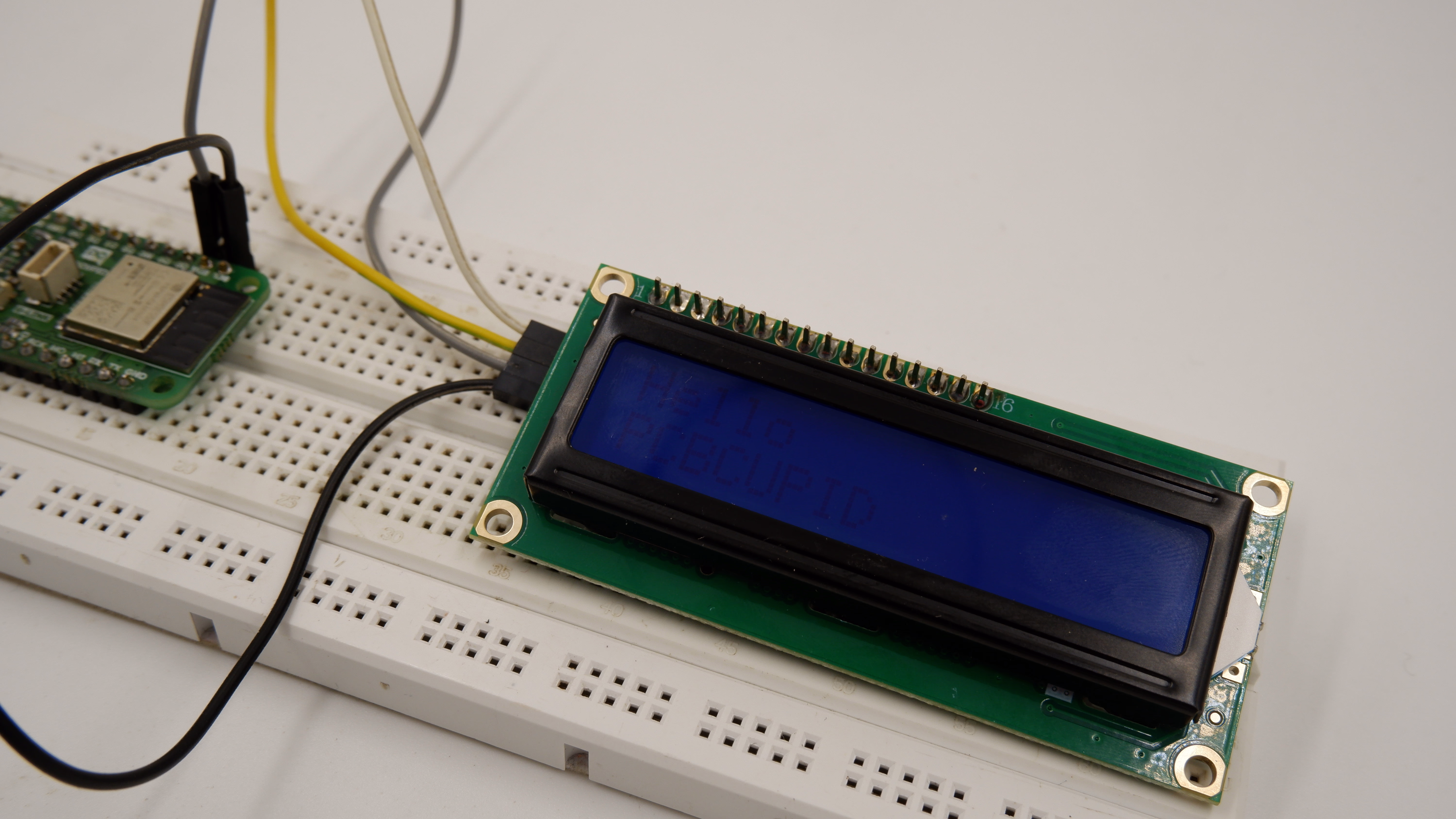
// Print text
lcd.setCursor(0, 0);
lcd.print("Hello");
lcd.setCursor(0, 1);
lcd.print("PCBCUPID");
}
void loop() {
// Static display - nothing needed
}
Step 4: Upload the Code
- Connect the Board
- Connect your GLYPH board to your computer
- Select the Board and Port
Do the following settings in your Arduino IDE,
Tools > Board > esp32 > Pcbcupid Glyph S3
For the Pcbcupid Glyph S3 to appear under Tools > Board > esp32, the esp32 board version installed in the Arduino IDE should be greater or equal to 3.1.0.
Tools > Port and select the port connected to your GLYPH.Tools > USB CDC on Boot > Enabled
If USB CDC on BOOT not enabled, you won’t be seeing any serial data on Arduino IDE.
-
Upload the Code
- Click the upload button (➡️ icon) or use the shortcut
CRTL + U in Arduino IDE to upload the code to the board.
Step 5: Observe Output on Serial Monitor