OLED Display Test for Glyph using SH1106 & SSD1306
1. Using SH1106 OLED Display
 The SH1106 is an OLED driver IC commonly used in 128x64 pixel monochrome OLED displays. It can communicate with microcontrollers via I2C, SPI, or parallel interfaces. While similar to the SSD1306, it has some differences, particularly in memory mapping and buffer size.
It’s made by Sino Wealth and is often found in 0.96”, 1.3”, and similar small OLED modules used in electronics projects.
The SH1106 is an OLED driver IC commonly used in 128x64 pixel monochrome OLED displays. It can communicate with microcontrollers via I2C, SPI, or parallel interfaces. While similar to the SSD1306, it has some differences, particularly in memory mapping and buffer size.
It’s made by Sino Wealth and is often found in 0.96”, 1.3”, and similar small OLED modules used in electronics projects.
2. Using SSD1306 OLED Display
 This guide demonstrates how to use an OLED display with the GLYPH Boards,initializing the display, drawing shapes, and displaying text like PCB Cupid and Generating PCB Cupid’s Logo on the display,assuming you are using GLYPH-C3 (but any GLYPH development board from the ESP32 Series should work).
The SSD1306 is a display driver IC made by Solomon Systech. It’s used to control monochrome OLED displays — most commonly the 0.96-inch 128x64 pixel modules used in electronics projects.
The SSD1306 isn’t the screen itself — it’s the chip inside the display module that handles communication and controls the screen.
This guide demonstrates how to use an OLED display with the GLYPH Boards,initializing the display, drawing shapes, and displaying text like PCB Cupid and Generating PCB Cupid’s Logo on the display,assuming you are using GLYPH-C3 (but any GLYPH development board from the ESP32 Series should work).
The SSD1306 is a display driver IC made by Solomon Systech. It’s used to control monochrome OLED displays — most commonly the 0.96-inch 128x64 pixel modules used in electronics projects.
The SSD1306 isn’t the screen itself — it’s the chip inside the display module that handles communication and controls the screen.
- How SSD1306 & SH1106 Work – Step-by-Step Both SSD1306 and SH1106 operate in similar ways, with just a few internal differences. Let’s explain the general process first:
- Microcontroller Sends Data Your microcontroller (like ESP32, Arduino, GLYPH board) sends commands and pixel data to the display through I2C or SPI interface. There are two types of data: Commands – for things like turning the display on/off, setting contrast, clearing the screen, etc. Display data – tells the display which pixels to light up (image, text, graphics).
- Driver IC Stores the Data in Display RAM Each chip (SSD1306 or SH1106) has internal Display RAM (called GDDRAM): SSD1306 → 128 x 64 bits = 1024 bytes SH1106 → 132 x 64 bits = 1056 bytes Each bit in the memory = 1 pixel (since the displays are monochrome: black or white) So when you send data like display.print(“Hello”), it gets translated into pixel positions and stored in this internal RAM.
- Data is Transferred to OLED Panel The driver IC then continuously refreshes the screen using the data in its RAM. It lights up each pixel based on the bit value stored (1 = ON, 0 = OFF). It scans through the rows and columns using multiplexing. Think of it like a movie projector: the driver IC shows what’s in its memory onto the screen over and over.
- Refresh Cycle Happens Rapidly The display is refreshed dozens of times per second (usually 60–100 Hz), which keeps the image stable and flicker-free. You don’t have to manage this refresh manually — the driver chip does it automatically.
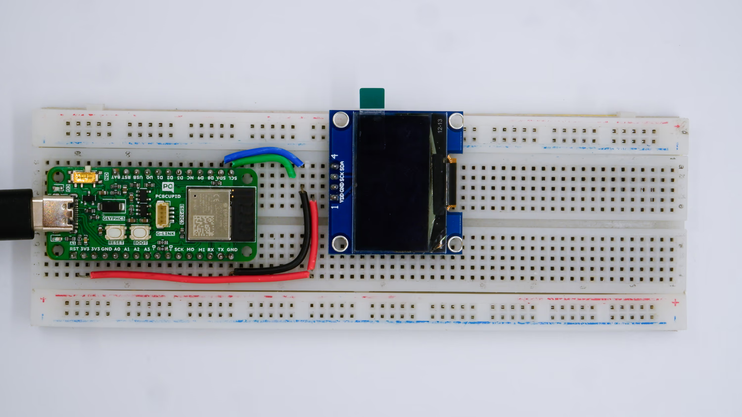
Step 1: Hardware Required
- Glyph Board
- Either SH1106 or SSD1306 OLED Display
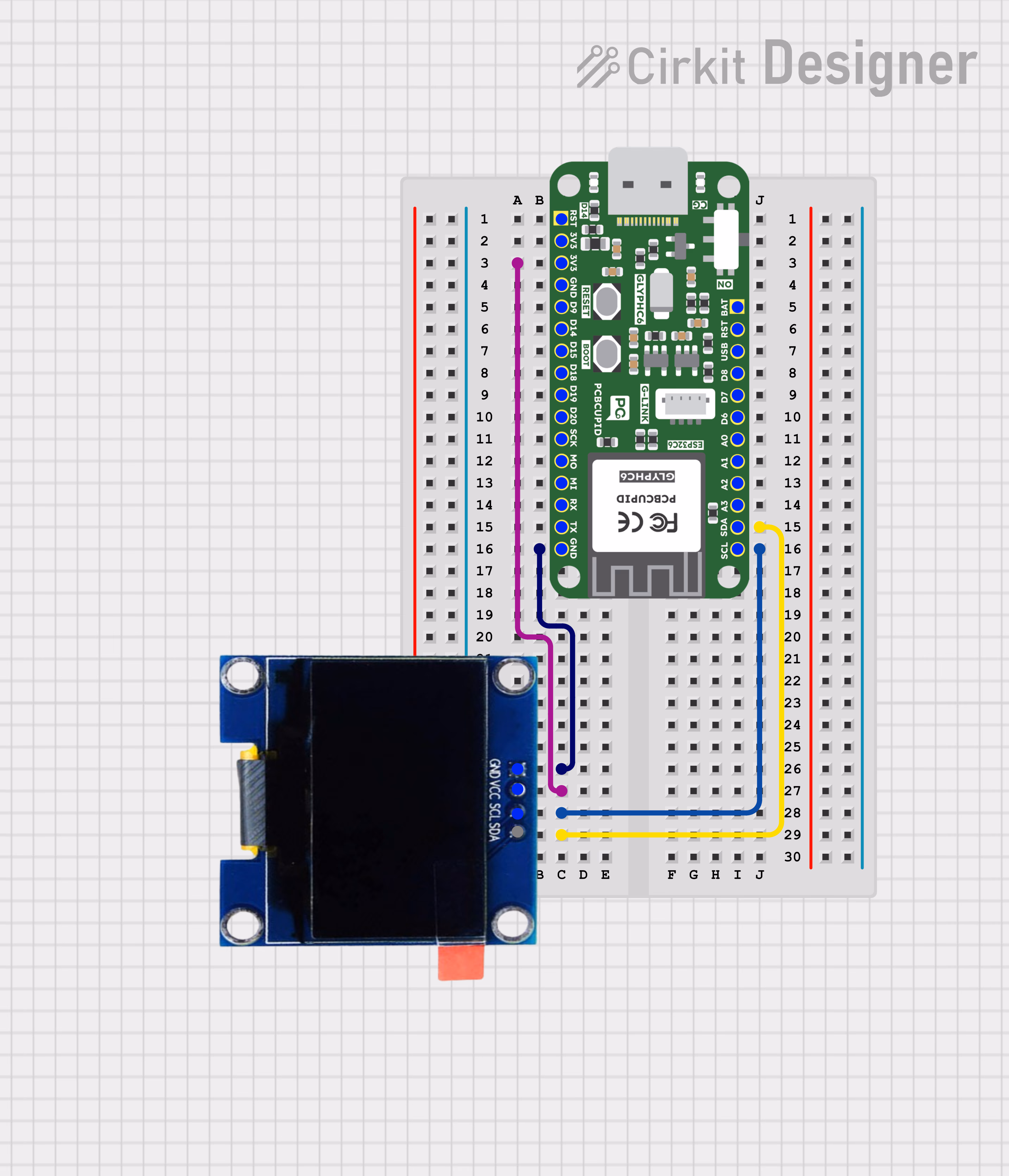
Step 2: Circuit Diagram
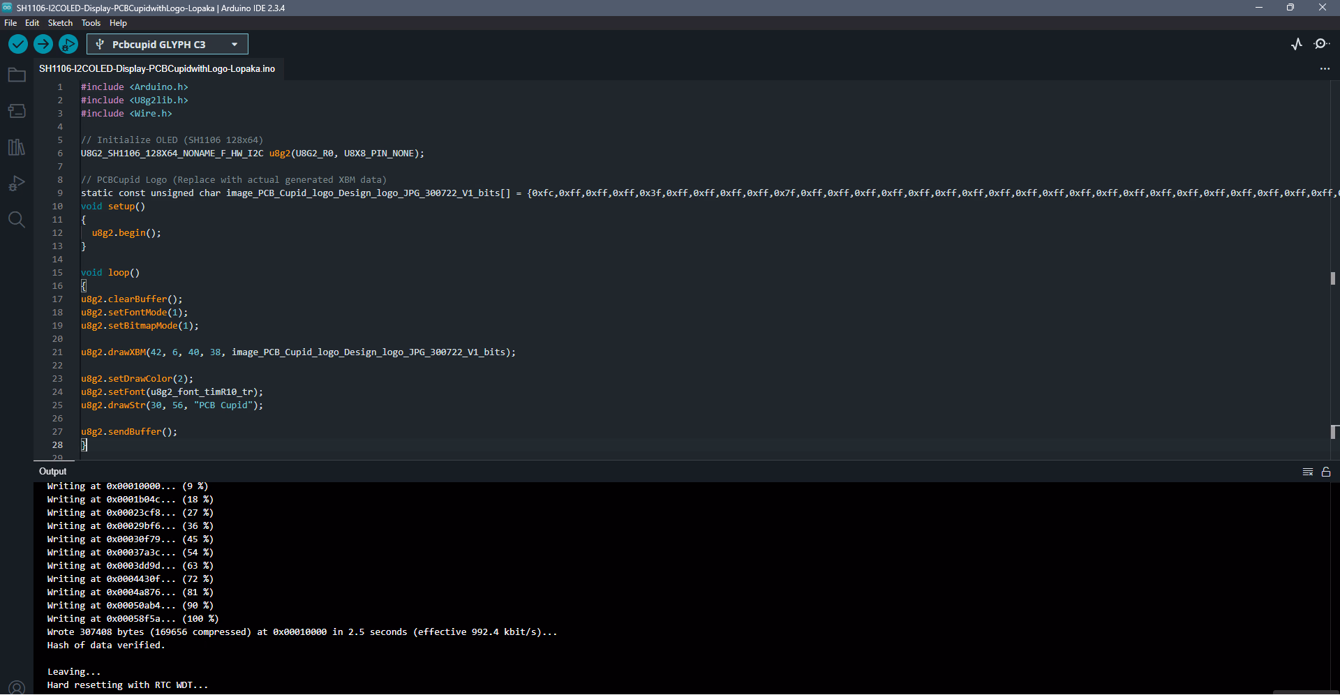
Step 3: Code Setup
- Open Arduino IDE.
-
Install the U8g2 library by going to
Sketch > Include Library > Manage Librariesand search for U8g2 library by olikraus - Copy and paste the following code into the Arduino IDE:
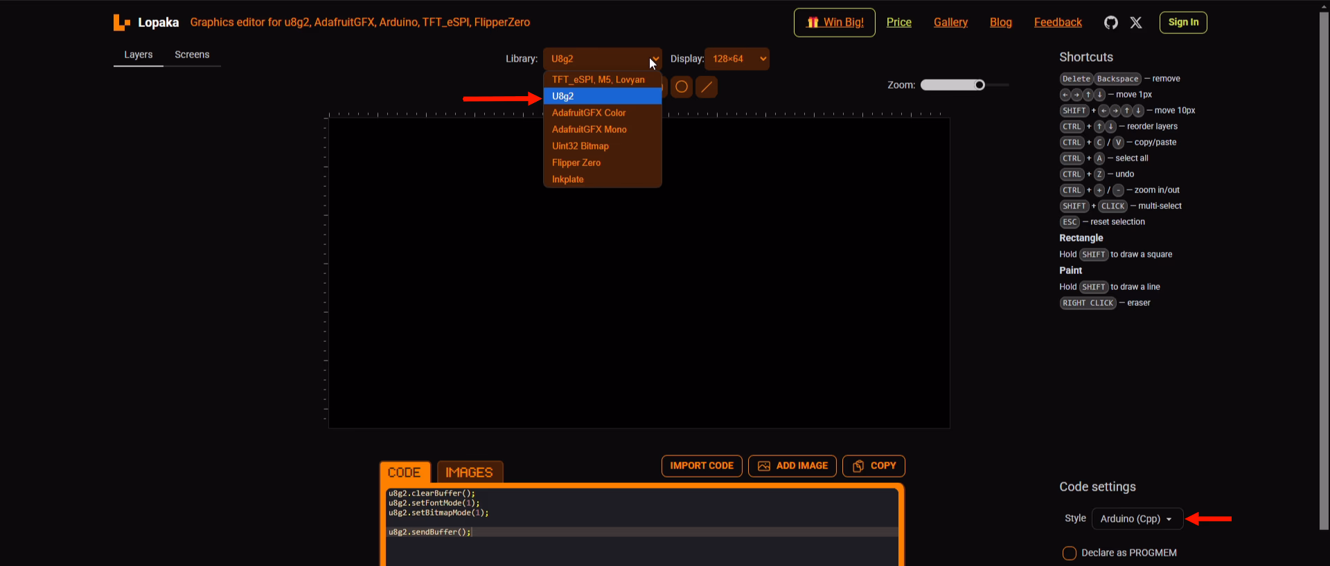
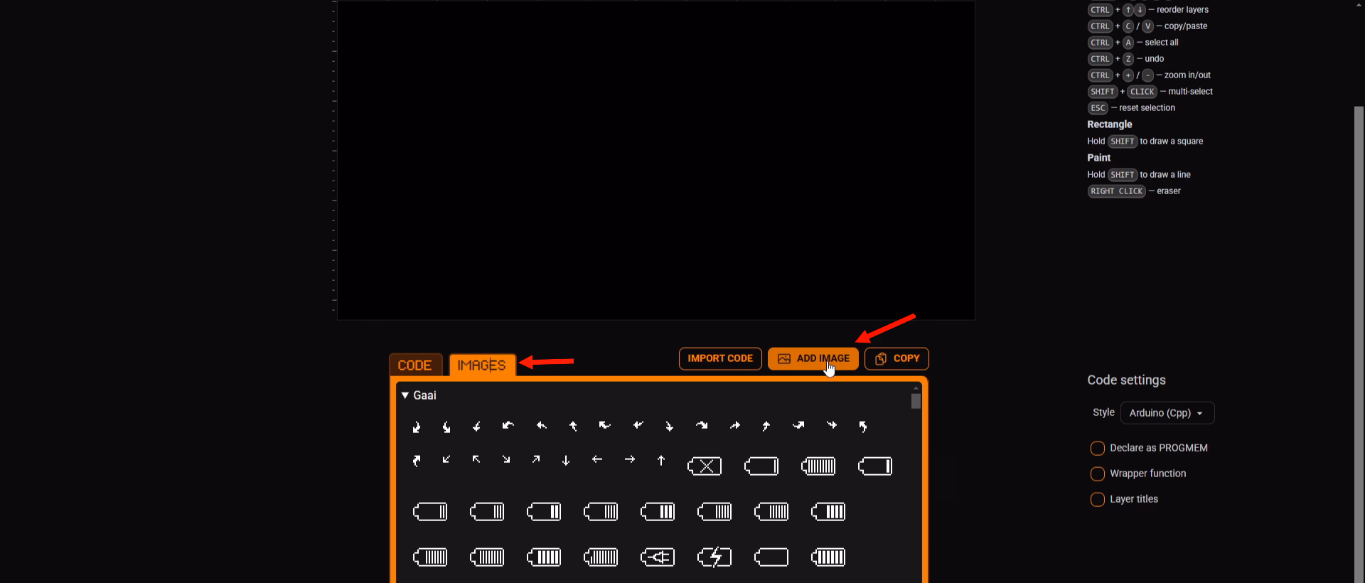
Code for SH1106 OLED Display
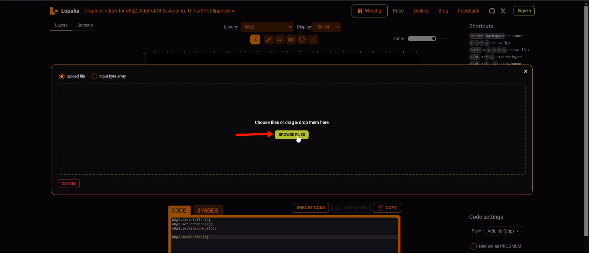
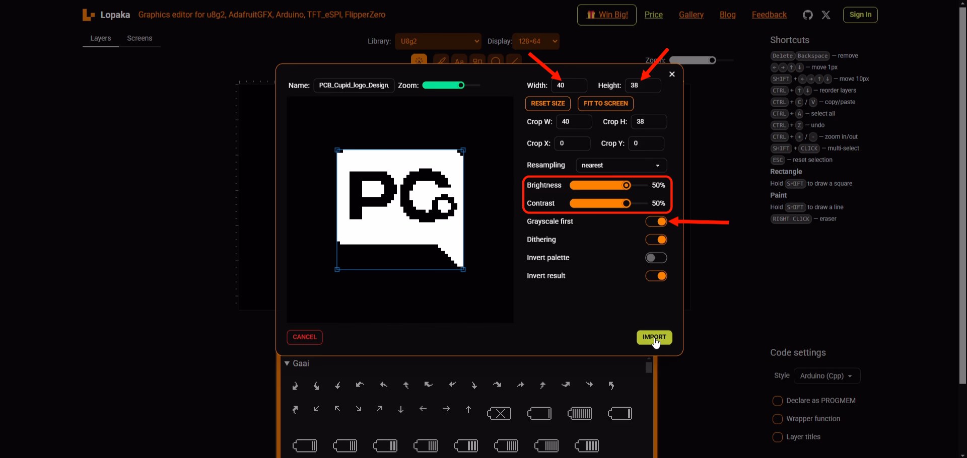
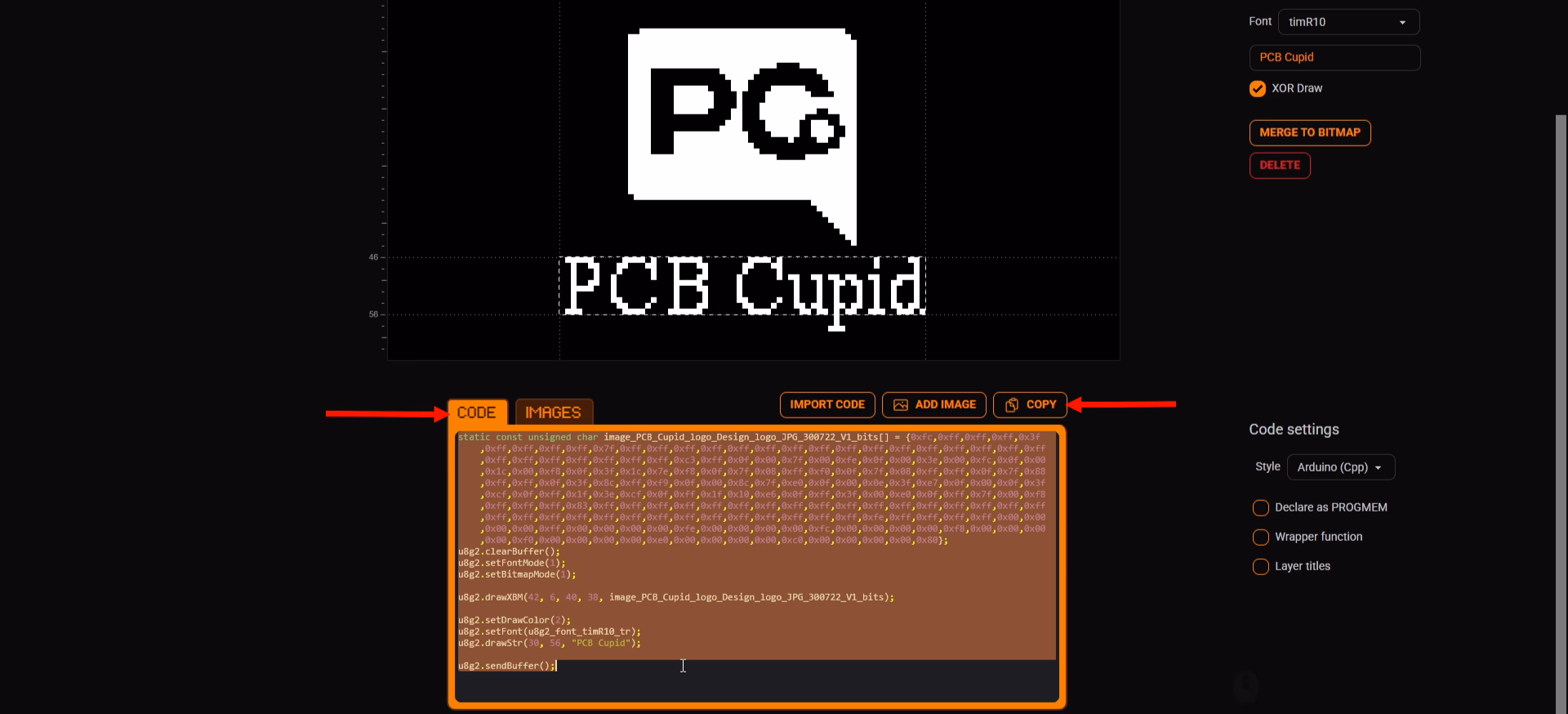
- Go to the website named Lopaka. Then do as in these Images:
Code for SSD1306 OLED Display
-
Install the Adafruit SD1306 & Adafruit GFX Libraries by Adafruit by going to
Sketch > Include Library > Manage Librariesand searching for these libraries - Copy and paste the following code into the Arduino IDE:
Step 4: Upload the Code
- Connect the Board
- Connect your GLYPH board to your computer
-
Select the Board and Port
Do the following settings in your Arduino IDE,
Do the following settings in your Arduino IDE,
Tools > Board > esp32 > Pcbcupid GLYPH C3
Tools > Portand select the port connected to your GLYPH.Tools > USB CDC on Boot >Enabled
- Upload the Code
- Click the upload button (➡️ icon) or use the shortcut
CTRL + Uin Arduino IDE to upload the code to the board.
Step 5: Observe Output on your OLED Display
After uploading the code for SH1106 OLED Display to the GlyphC3 board, the SH1106 OLED displays the Logo of PCB CUPID along with the text PCBCUPID, both centrally aligned, like this: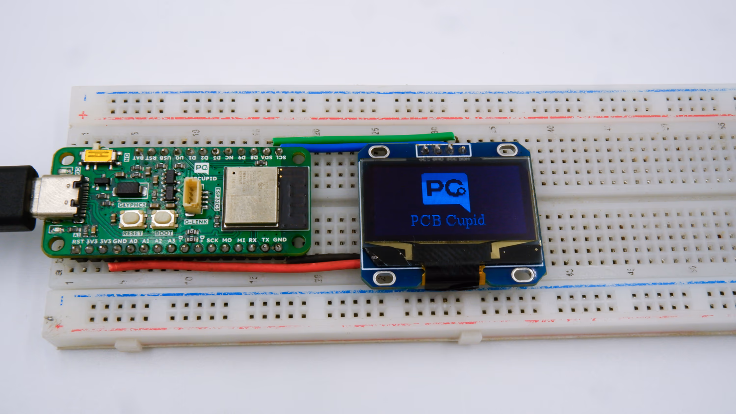 After uploading the code for SSD1306 OLED Display to the GlyphC3 board, the SSD1306 OLED displays the text PCBCUPID.