Interfacing an Ultrasonic Sensor with GLYPH-C6
Introduction
Ultrasonic sensors are electronic devices that calculate the target’s distance by emission of ultrasonic sound waves and convert those waves into electrical signals. The speed of emitted ultrasonic waves is faster than the audible sound.
Working Principle of Ultrasonic sensor
Ultrasonic sensor working principle is either similar to SONAR or RADAR which evaluates the target/object attributes by understanding the received echoes from sound/radio waves correspondingly.
This guide will help you interface an HC-SR04 Ultrasonic Sensor with a GLYPH-C6 board.
The HC-SR04 has mainly two essential elements- the transmitter and receiver. Using the piezoelectric crystals, the transmitter generates sound, and from there it travels to the target and gets back to the receiver component. The HC-SR04 Sensor emits ultrasonic waves at a frequency of around 40,000 Hz (though the actual frequency may vary slightly). These waves travel through the air until they encounter an object in their path. Upon hitting the object, the waves bounce back to the sensor.
By measuring the time, it takes for the ultrasonic pulse to travel to the object and return, and knowing the speed of sound in air (approximately 340 meters per second at room temperature), you can accurately calculate the distance between the sensor and the object.
To initiate the ultrasound emission, we set the Trig pin to a High state for 10 microseconds. This action triggers the transmission of an 8-cycle ultrasonic burst, traveling at the speed of sound. Immediately after sending this burst, the Echo pin goes high, indicating its readiness to receive the reflected wave from any objects in the vicinity.
If there’s no object or reflected pulse detected, the Echo pin will return to a low state after 38 milliseconds due to a timeout. If there is a reflected pulse, causes the Echo pin to transition to a low state before the 38-millisecond timeout. By measuring the duration for which the Echo pin remains HIGH, we can ascertain the distance traveled by the sound wave, and consequently, the distance from the sensor to the object.
The formula for calculating distance using the HC-SR04 sensor is:
Distance = (Time taken by the wave to return(T) x Speed of sound(S) ) / 2
S corresponds to Sound speed = 343 measured in m/sec
This formula divides the time by 2 because the wave travels from the sensor to the object and back again, so the total distance traveled is twice the distance between the sensor and the object.
Here is a concise summary of its characteristics:
-
Power Supply: +5V DC
-
Quiescent Current: < 2mA
-
Working Current: 15mA
-
Effectual Angle: < 15
-
Ranging Distance: 2cm – 400 cm
-
Resolution: 0.3 cm
-
Measuring Angle: 30 degrees
-
Trigger Input Pulse width: 10uS TTL pulse
-
Echo Output Signal: TTL pulse proportional to the distance range
-
Dimensions: 45mm x 20mm x 15mm
You can interface the HC-SR04 sensor with microcontrollers like Arduino, Raspberry Pi, or any other microcontroller that supports GPIO (General Purpose Input Output). By reading the signal from the Echo pin, you can measure the time taken for the ultrasonic pulse to return, and hence calculate the distance using the formula mentioned above. The HC-SR04 ultrasonic sensor is widely used in applications owing to its precision in distance measurement using sound waves.
Here’s a breakdown of some prevalent uses:
-Robotics: Within robotics, it serves purposes such as obstacle detection, evasion, pathfinding, and environment mapping.
-Speed and Direction Measurement: The sensor is adept at determining speed and direction between two entities.
-Medical Appliances: It finds application in medical ultrasonography, offering a non-invasive means to examine the body.
-Burglar Alarms: Integrating the sensor into security setups enables intruder detection.
-Sonar Systems: Underwater, it aids sonar equipment in object detection.
-Humidifiers: In the realm of humidifiers, it aids in gauging water levels.
-Wireless Charging: The sensor plays a role in aligning devices for efficient wireless charging.
-Non-Destructive Testing: Its utilization in inspecting materials and structures without causing harm proves invaluable.
These applications capitalize on the sensor’s non-contact detection capabilities, delivering both safety and convenience across diverse domains. While the HC-SR04 Ultrasonic Sensor is a versatile and widely used component for distance measurement in various projects, it does have some limitations.
Here are the constraints or limitations on its usage:
-Limited Range: The HC-SR04 sensor has a maximum range typically around 2 meters, beyond which accuracy decreases.
-Blind Spots: The sensor may struggle to detect objects with irregular shapes or surfaces that absorb sound waves, leading to blind spots in detection.
-Angle Dependency: Accuracy may vary based on the angle of incidence of the sound waves, affecting the reliability of distance measurements.
-Interference: Environmental factors such as noise and other ultrasonic sources can interfere with sensor readings, potentially leading to inaccuracies.
-Temperature Sensitivity: The speed of sound in air, which the sensor relies on for distance calculation, can vary with temperature, affecting measurement accuracy.
-Resolution: The sensor’s resolution may not be fine enough for applications requiring precise distance measurements, as it typically provides distance readings in centimeters.
-Limited Functionality in Certain Conditions: HC-SR04 may encounter challenges in highly reflective or absorbent environments, affecting its performance.
Step 1: Hardware Required
- Glyph Boards
- HC-SR04 Ultrasonic Sensor
- Jumper wires
- Breadboard (optional)
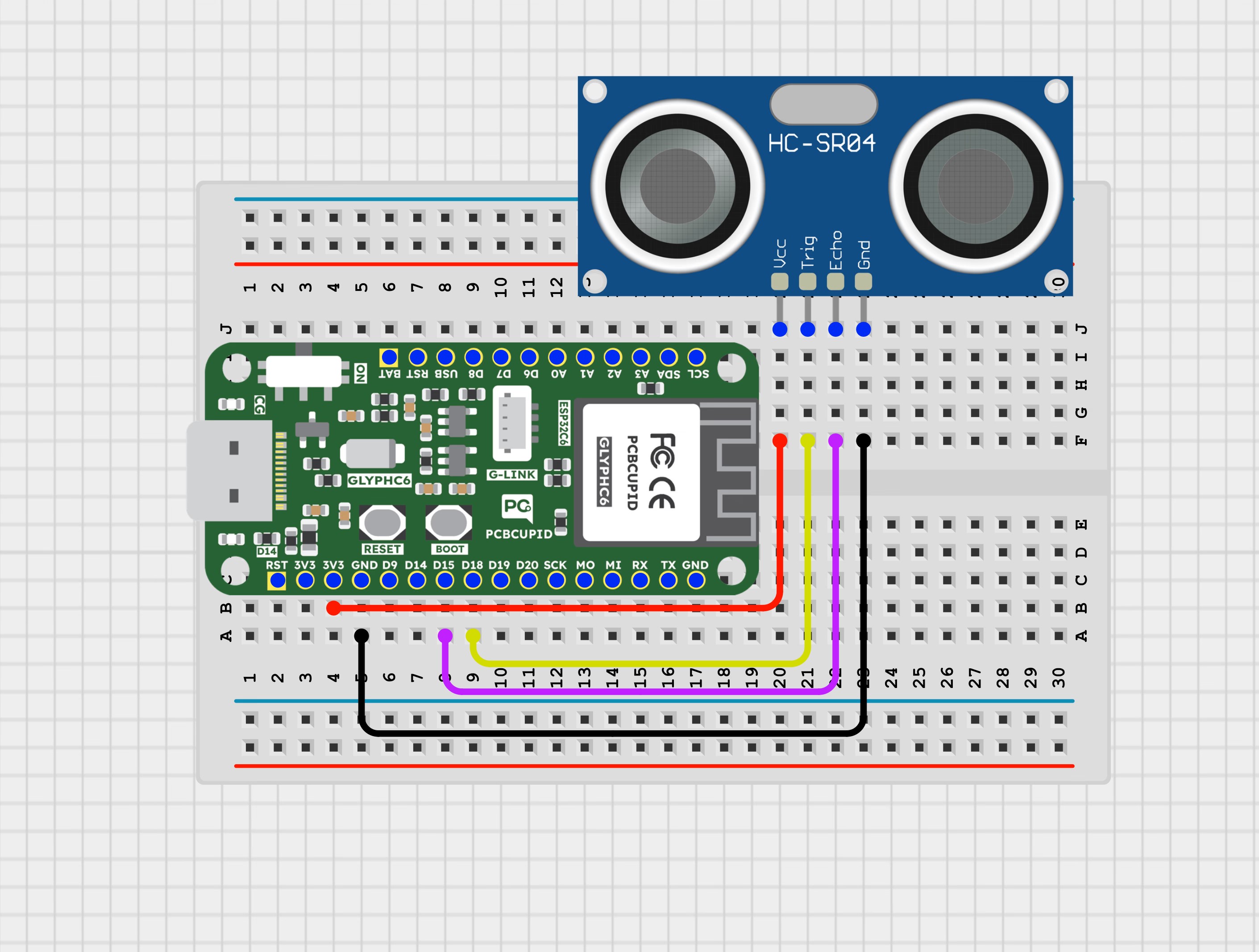
Step 2: Circuit Diagram
Connect the HC-SR04 sensor to the GLYPH-C6 board using the following pin configurations:
- VCC to 5V (Standard HC-SR04 requires 5V)
- GND to GND
- TRIG to GPIO 18
- ECHO to GPIO 15
Step 3: Code Setup
-
Open Arduino IDE
-
Enter the following code into the Arduino IDE
Step 4: Upload the Code
- Connect the Board
- Connect your GLYPH board to your computer
-
Select the Board and Port
Do the following settings in your Arduino IDE,
Tools > Board > esp32 > Pcbcupid GLYPH C6
For the Pcbcupid GLYPH C6 to appear under Tools > Board > esp32, the esp32 board version installed in the Arduino IDE should be greater or equal to 3.1.0.
Tools > Port and select the port connected to your GLYPH.Tools > USB CDC on Boot > Enabled
If USB CDC on BOOT is not enabled, you won’t see any serial data in the Arduino IDE.
- Upload the Code
- Click the upload button (➡️ icon) or use the shortcut
CTRL + U in Arduino IDE to upload the code to the board.
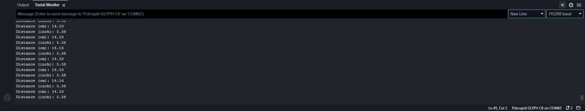
Step 5: Check the Output on Serial Monitor
The Serial Monitor will display the distance to the detected object in cm as well as inches