Interfacing an LDR with GLYPH board
An LDR (Light Dependent Resistor), also known as a photoresistor, is a variable resistor that changes its resistance based on the intensity of light falling on it.
How an LDR Works:
Light Intensity vs. Resistance:
In darkness, the resistance of an LDR is very high (in the range of megaohms, MΩ).
In bright light, the resistance drops significantly (to a few hundred ohms, Ω).
Material Composition:
LDRs are made of semiconductor materials like cadmium sulfide (CdS), which have high resistance in darkness but become more conductive when exposed to light (due to photon energy freeing electrons).
LDR in a Circuit:
Voltage Divider Circuit:
An LDR is often used in a voltage divider with a fixed resistor to convert changes in light intensity into voltage variations.
The voltage across the LDR can be measured using a microcontroller (e.g., ESP32, Arduino).
Controlling Devices:
LDRs are used in automatic streetlights, light meters, and solar tracking systems to control relays, LEDs, or other devices based on ambient light levels.
Step 1: Hardware Required
- GLYPH Board
- Light Dependent Resistor (LDR)
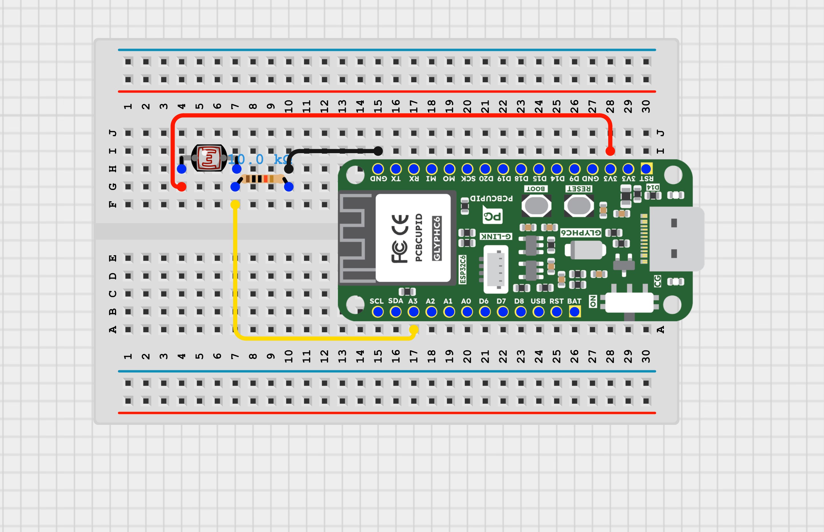
Step 2: Circuit Diagram
Step 3: Code Setup
Step 4: Upload the Code
- Connect the Board
- Connect your GLYPH board to your computer
-
Select the Board and Port
Do the following settings in your Arduino IDE,
- Tools > Board > esp32 > Pcbcupid GLYPH C6
For the Pcbcupid GLYPH C6 to appear under Tools > Board > esp32, the esp32 board version installed in the Arduino IDE should be greater or equal to 3.1.0.
- Tools > Port and select the port connected to your GLYPH.
- Tools > USB CDC on Boot > Enabled
If USB CDC on BOOT is not enabled, you won’t see any serial data in the Arduino IDE.
- Upload the Code
Upload the corresponding code for your board to the GLYPH board using the Arduino IDE.
- Click the upload button (➡ icon) or use the shortcut CTRL + U in Arduino IDE to upload the code to the board.
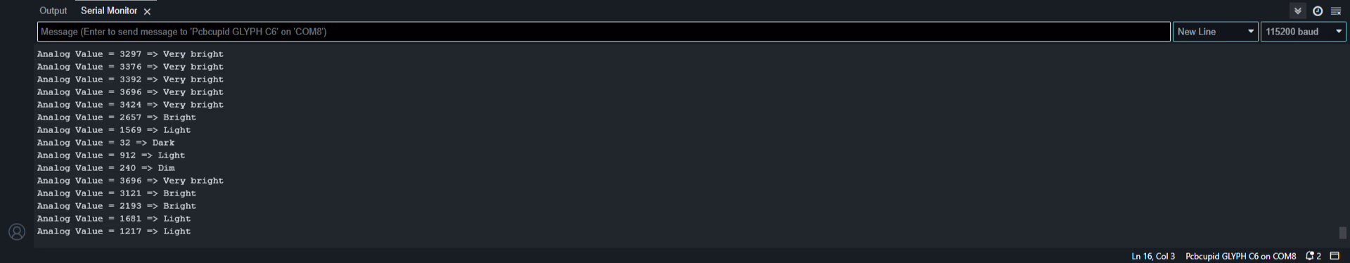
Step 5: Observe the Serial Monitor Output
Try covering and uncovering the LDR with your hand to block and pass light, and observe the output on the Serial Monitor.