One Wire Communication using DHT22 & GLYPH
One-wire communication is a serial communication protocol that enables data transfer between devices using a single data wire (along with ground). It allows bidirectional data exchange without requiring additional clock or synchronization lines, making it highly efficient for low-speed, low-power applications such as sensor interfacing. How One-Wire Communication Works: The communication follows a sequence of steps between a master (e.g., microcontroller) and slave (e.g., sensor).- Initialization Phase The master device pulls the data line LOW for a specific duration (e.g., 480µs in DHT22). This signals the slave device to get ready for communication.
- Presence Response The slave device detects the start signal. It responds by pulling the data line LOW for a short time (e.g., 80µs) and then releases it back to HIGH. This indicates that the slave is ready to communicate.
- Data Transmission (Bit Encoding) Data is sent bit by bit using pulse width modulation (PWM): Bit ‘0’ → A long LOW pulse (~80µs) Bit ‘1’ → A short LOW pulse (~26µs)
- The receiver measures the duration of the LOW pulse to determine whether the bit is 0 or 1. The receiver reads the incoming bits, assembles them into bytes, and then processes the data accordingly.
- End of Communication Once all data is transmitted, the line is released to HIGH (idle state).
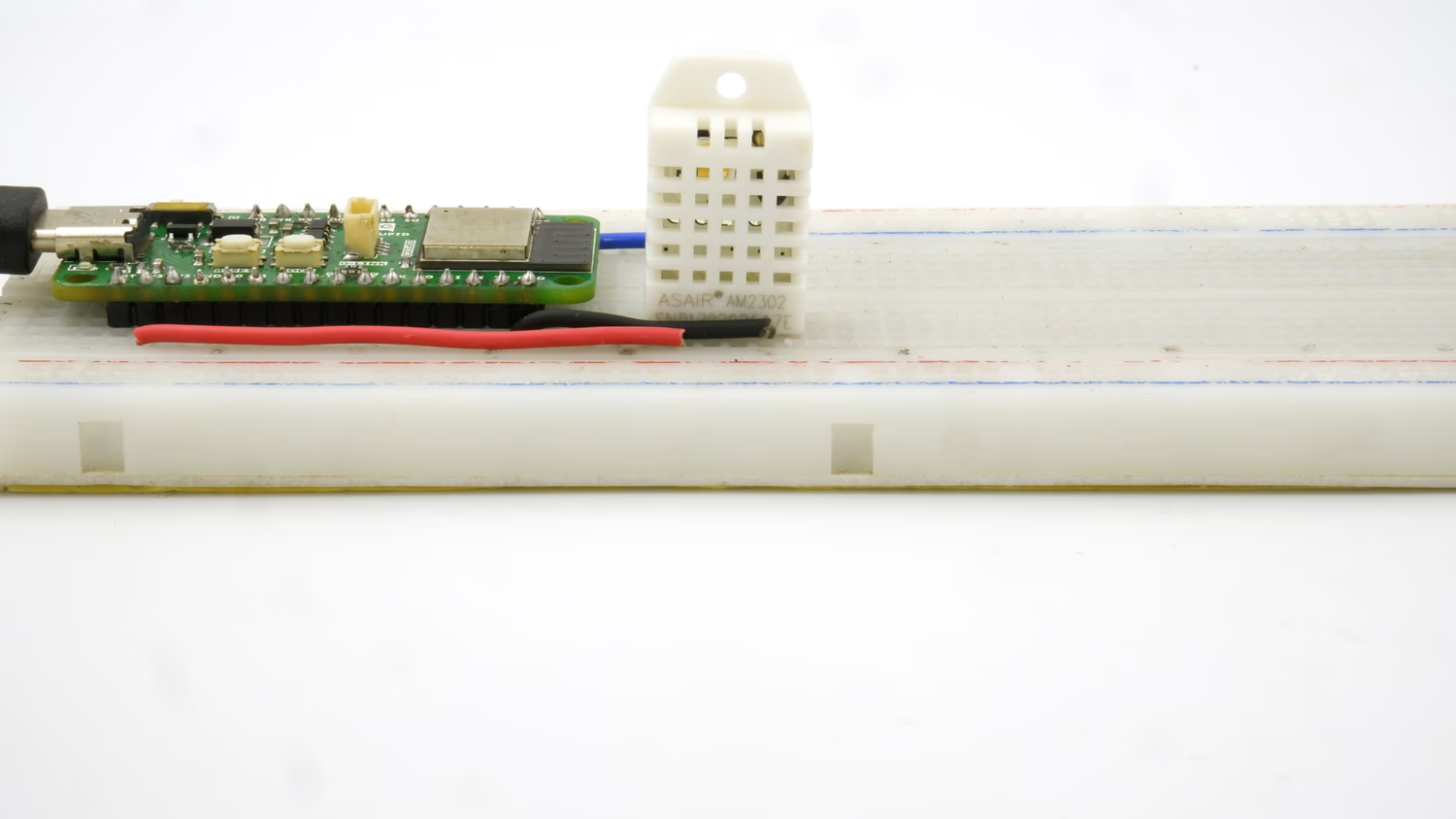 This guide will help you interface a DHT22 Sensor Module with a GLYPH board to read and display Humidity, Temperature and Heat Index of the surrounding air, assuming you are using GLYPH-C3 (but any GLYPH development board from the ESP32 Series should work)
The DHT22 sensor is a Digital sensor that measures Humidity values in Percentage in Relative Humidity(20 to 90%) and Temperature values in degree Celsius(0 to 50°C).
Relative humidity is the ratio of water vapor in the air to the maximum amount of water vapor the air can hold.
Heat Index is a calculated value that combines Air Temperature and Relative Humidity to estimate how hot it actually feels in a given location.
DHT11/DHT22 uses a Capacitive Humidity sensor and a Thermistor to measure the air around it and outputs a Digital signal on the Data pin. It requires a power supply of 3 to 5.5 Volts DC.
This guide will help you interface a DHT22 Sensor Module with a GLYPH board to read and display Humidity, Temperature and Heat Index of the surrounding air, assuming you are using GLYPH-C3 (but any GLYPH development board from the ESP32 Series should work)
The DHT22 sensor is a Digital sensor that measures Humidity values in Percentage in Relative Humidity(20 to 90%) and Temperature values in degree Celsius(0 to 50°C).
Relative humidity is the ratio of water vapor in the air to the maximum amount of water vapor the air can hold.
Heat Index is a calculated value that combines Air Temperature and Relative Humidity to estimate how hot it actually feels in a given location.
DHT11/DHT22 uses a Capacitive Humidity sensor and a Thermistor to measure the air around it and outputs a Digital signal on the Data pin. It requires a power supply of 3 to 5.5 Volts DC.
DHT22 is overall better in terms of performance & accuracy compared to DHT11
Step 1: Hardware Required
- GLYPH-C3 Board
- DHT22 Sensor
- 4.7k / 10k Ohm Resistor(Optional)
- Breadboard
- Jumper Wires
Step 2: Circuit Diagram
You can use either the DHT22 Sensor or it’s Module.In the present example, we use the DHT22 Sensor.The Circuit diagram with DHT22 Sensor is given below: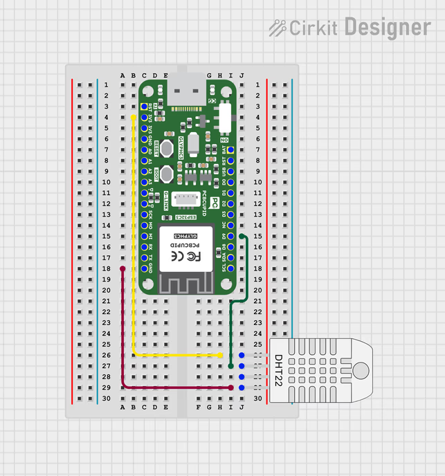
As shown in the figure, If you are using just the DHT22 Sensor, then it will have 4 pins, unlike the modules which expose only 3-pin.
- Connect pin 1 (on the left) of the sensor to +3.3V of the GLYPH board
- Connect pin 2 of the sensor to the DHTPIN D0 of the GLYPH board
- Pin 3 is a No-Connect (NC) Pin. So, no need to use that pin. This pin is not present in the DHT11 Sensor Module
- Connect pin 4 (on the right) of the sensor to GROUND of the GLYPH board (This is Pin 3 of the Module)
- (Optional) Connect a 10K or a 4.7K Ohm pull-up resistor from pin 2 (data) to pin 1 (VCC or power pin) of the sensor - You require a pull-up resistor between the data wire and VCC because the DHT11 uses a Bidirectional Communication system on a Single Wire. When neither end is communicating, both ends of the link will be in high impedance mode - i.e., input mode. In that case, the signal will be floating and needs the pull-up to keep it in a known state. This is not needed if you are using a Sensor Module, as the Module already has an in-built pull-up resistor.
Step 3: Code Setup
- Open Arduino IDE
- Install the Necessary Libraries
- Open your Arduino IDE and go to
Sketch > Include Library > Manage Libraries. The Library Manager should open. - Search for Adafruit DHT on the Search box and install the DHT sensor library by Adafruit.
- After installing the Adafruit DHT library, search for Adafruit Unified Sensor library and install it.
- After installing the libraries, restart your Arduino IDE.
- Enter the following code into the Arduino IDE
Step 4: Upload the Code
- Connect the Board
- Connect your GLYPH board to your computer
-
Select the Board and Port
Do the following settings in your Arduino IDE,
Do the following settings in your Arduino IDE,
Tools > Board > esp32 > Pcbcupid GLYPH C3
Tools > Portand select the port connected to your GLYPH.Tools > USB CDC on Boot >Enabled
- Upload the Code
- Click the upload button (➡️ icon) or use the shortcut
CTRL + Uin Arduino IDE to upload the code to the board.
Step 5: Observe the Output on the Serial Monitor
The Serial Monitor should start displaying the Humidity, Temperature and Heat Index values of the surrounding air like this: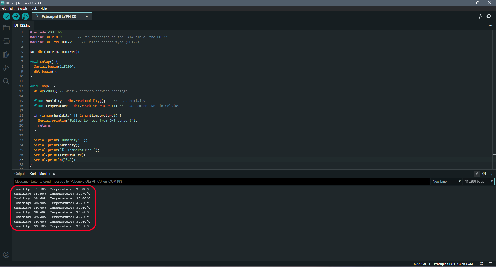 If you place your finger on the DHT11 sensor or blow some air onto the sensor (or even light a Flame Lighter and hold it near the DHT11 sensor), then you will see the readings change appropriately.