Interfacing an IR Sensor with GLYPH
Introduction
An IR sensor is an electronic device that emits Infrared (IR) light to sense objects in its surroundings. The IR sensor can measure the heat of an object and detect motion. Usually, in the infrared spectrum, all objects radiate some form of thermal radiation. This radiation is invisible to our eyes, but the IR sensor can detect it.
The emitter is an IR LED (Light Emitting Diode) and the detector is an IR photodiode. A photodiode is sensitive to IR light of the same wavelength emitted by the IR LED. When IR light falls on the photodiode, its resistance and output voltage change in proportion to the magnitude of the IR light received.
There are five basic elements used in a typical infrared detection system:
-
An infrared source - Infrared lasers and Infrared LED’s of specific wavelength used as infrared sources.
-
A transmission medium
-
An optical component
-
Infrared detectors or receivers
-
Signal processing
The three main types of media used for infrared transmission are vacuum, atmosphere and optical fibers. Optical components are used to focus the infrared radiation or to limit the spectral response.
There are different types of infrared transmitters depending on their wavelengths, output power and response time. An IR sensor consists of an IR LED and an IR Photodiode. Together, they form an optical pair often used for object detection.
IR Transmitter or IR LED
Infrared Transmitter is a light emitting diode (LED) which emits infrared radiation. Even though an IR LED looks like a normal LED, the radiation emitted by it is invisible to the human eye. The image below shows an IR receiver/photodiode:
IR Receiver or Photodiode
Infrared Receivers or infrared sensors detect the radiation from an IR transmitter. IR receivers come in the form of photodiodes and phototransistors. Infrared Photodiodes are different from normal photo diodes as they detect only infrared radiation. Below image shows the picture of an IR receiver,
Different types of IR receivers exist based on the wavelength, voltage, package, etc. When used in an infrared transmitter – receiver combination, the wavelength of the receiver should match with that of the transmitter.
The emitter is an IR LED and the detector is an IR photodiode. The IR photodiode is sensitive to the IR light emitted by an IR LED. The photo-diode’s resistance and output voltage change in proportion to the IR light received. This is the underlying working principle of the IR sensor.
When the IR transmitter emits radiation, it reaches the object, and some of it reflects back to the IR receiver. Based on the intensity of the reflection, the sensor’s output is defined.
IR Sensor Circuit
An IR Sensor’s circuit can be built with a photodiode, IR LED, an Op-Amp, LED & a potentiometer, The main function of an infrared LED is to emit IR light and the photodiode is used to sense the IR light. In this circuit, an operational amplifier is used as a voltage comparator and the output of the sensor can be adjusted by the potentiometer based on the requirement.
Once the light generated from the infrared LED can be dropped on the photodiode once striking an object, then the photodiode’s resistance will be dropped.
Here, op-amp’s one of the input at threshold value can be set through the potentiometer whereas other inputs can be set by using the series resistor of the photodiode. Once the radiation on the photodiode is more, then the voltage drop will be more across the series resistor. In the operational amplifier, both the voltages are evaluated.
If the series resistor’s voltage is higher than the threshold voltage then the IC output is high. When the IC output is given to an LED then it will blink. So using a potentiometer, the threshold voltage can be adjusted based on the conditions of surroundings.
In this circuit, the arrangement of the IR receiver and the IR LED is a very essential factor. Once the infrared LED is placed directly ahead of the infrared receiver, then this arrangement can be known as Direct Incidence.
So in this case, nearly the whole radiation from the infrared LED will drop on the infrared receiver. Therefore there is a row of view contact among the IR Tx & Rx. If a target drops in this row, it blocks the emission while approaching the receiver by reproducing or absorbing the radiation.
Advantages
-
Low power consumption
-
Noise immunity is strong
-
Detects motion when the light is present or absent
-
They do not need to get in touch with objects for detection.
-
No data leakage because of the directionality infrared radiation of ray
-
It responds very quickly as compared to thermocouples.
Disadvantages
-
Line of sight is necessary
-
It can be affected based on the conditions of the environment like fog, rain, pollution, dust, etc
-
These sensors can be blocked with common objects.
-
The data rate transmission is not fast
-
Range is limited
-
High force IR signals can harm human eyes
Applications of IR Sensor
IR sensors are used in various robotic projects, most commonly for path tracing in line follower robots and in various electronic devices. Some of its applications are:
-
Night Vision Devices- An Infrared technology implemented in night vision equipment if there is not enough visible light available to see unaided. Night vision devices convert ambient photons of light into electrons and then amplify them using a chemical and electrical process before finally converting them back into visible light.
-
Radiation Thermometers- IR sensors are used in radiation thermometers to measure the temperature depend upon the temperature and the material of the object and these thermometers have some of the following features
- Measurement without direct contact with the object
- Faster response
- Easy pattern measurements
-
Infrared Tracking-IR Sensor also finds use in tracking of Robots, Drones & Unmanned Aerial Vehicles and Missile technology. Infrared Tracking or Infrared Homing, is a missile guidance system which operates using the infrared electromagnetic radiation emitted from a target to track it.
-
IR Imaging Devices
Step 1: Hardware Required
-
GLYPH Board
-
IR Sensor
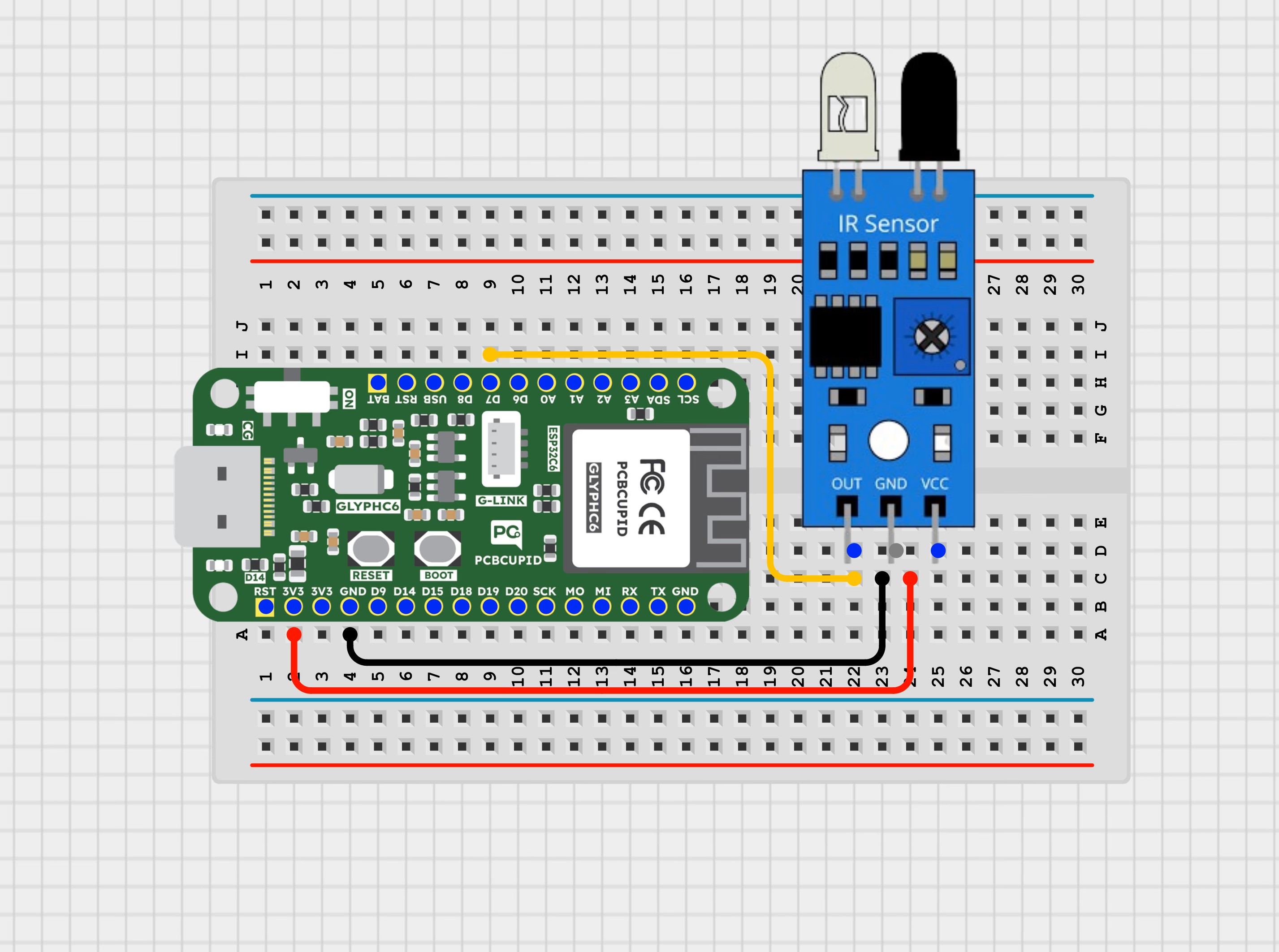
Step 2: Circuit Diagram
Step 3: Code Setup
Step 4: Upload the Code
- Connect the Board
Connect your GLYPH board to your computer
-
Select the Board and Port
Do the following settings in your Arduino IDE,
- Tools > Board > esp32 > Pcbcupid GLYPH C6
For the Pcbcupid Glyph to appear under Tools > Board > esp32, the esp32 board version installed in the Arduino IDE should be greater or equal to 3.1.0.
- Tools > Port and select the port connected to your GLYPH.
- Tools > USB CDC on Boot > Enabled
If USB CDC on BOOT is not enabled, you won’t see any serial data in the Arduino IDE.
- Upload the Code
Upload the corresponding code for your board to the GLYPH board using the Arduino IDE.
- Click the upload button (➡ icon) or use the shortcut CTRL + U in Arduino IDE to upload the code to the board.
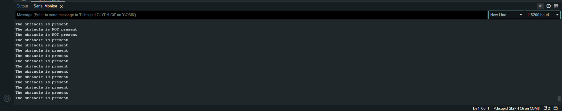
Step 5: Observe the Serial Monitor Output
Place your hand in front of the IR Sensor Transmitter LED and you will see the IR Sensor Module’s LED light up and the Serial Monitor showing that the Obstacle is detected