GLYPH I2C Scan
 This guide will walk you through performing an I2C Scan with a GLYPH board, assuming you are using GLYPH-C3 (but any GLYPH development board from the ESP32 Series should work).
The I2C (Inter-Integrated Circuit) protocol is a popular communication method for connecting various sensors and modules to Microcontrollers.
Developed by Philips Semiconductor (now NXP Semiconductors) in 1982, I2C was designed to provide a simple and efficient way for chips to communicate within electronic devices.
I2C uses just two bidirectional open-drain lines: SCL (Serial Clock Line) and SDA (Serial Data Line), making it a space-efficient and cost-effective solution for short-distance communication. Its multi-master capability and addressable nature allow multiple devices to share the same bus, which has contributed to its widespread adoption in various applications, from consumer electronics to automotive systems and IoT devices. In the I2C protocol, each device on the bus is identified by a unique 7-bit address, allowing multiple devices to share the same SCL and SDA lines as long as each device has a different/distinct address. This way, the microcontroller can communicate with each device individually by addressing them with their specific I2C addresses.
There are 4 methods how you can connect your GLYPH board via I2C:
This guide will walk you through performing an I2C Scan with a GLYPH board, assuming you are using GLYPH-C3 (but any GLYPH development board from the ESP32 Series should work).
The I2C (Inter-Integrated Circuit) protocol is a popular communication method for connecting various sensors and modules to Microcontrollers.
Developed by Philips Semiconductor (now NXP Semiconductors) in 1982, I2C was designed to provide a simple and efficient way for chips to communicate within electronic devices.
I2C uses just two bidirectional open-drain lines: SCL (Serial Clock Line) and SDA (Serial Data Line), making it a space-efficient and cost-effective solution for short-distance communication. Its multi-master capability and addressable nature allow multiple devices to share the same bus, which has contributed to its widespread adoption in various applications, from consumer electronics to automotive systems and IoT devices. In the I2C protocol, each device on the bus is identified by a unique 7-bit address, allowing multiple devices to share the same SCL and SDA lines as long as each device has a different/distinct address. This way, the microcontroller can communicate with each device individually by addressing them with their specific I2C addresses.
There are 4 methods how you can connect your GLYPH board via I2C:
1. Pre-Assigned pin on board (SDA,SCL)
This method is perfect if you are using GLYPH board settings on Arduino IDA as it’s officially supported by Arduino Core.
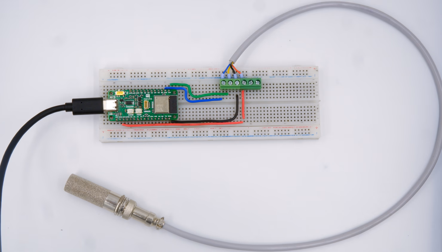
2. Through Terminal Blocks
You can use this method if you using one of our industrial sensor like SHT 35 & SHT 45
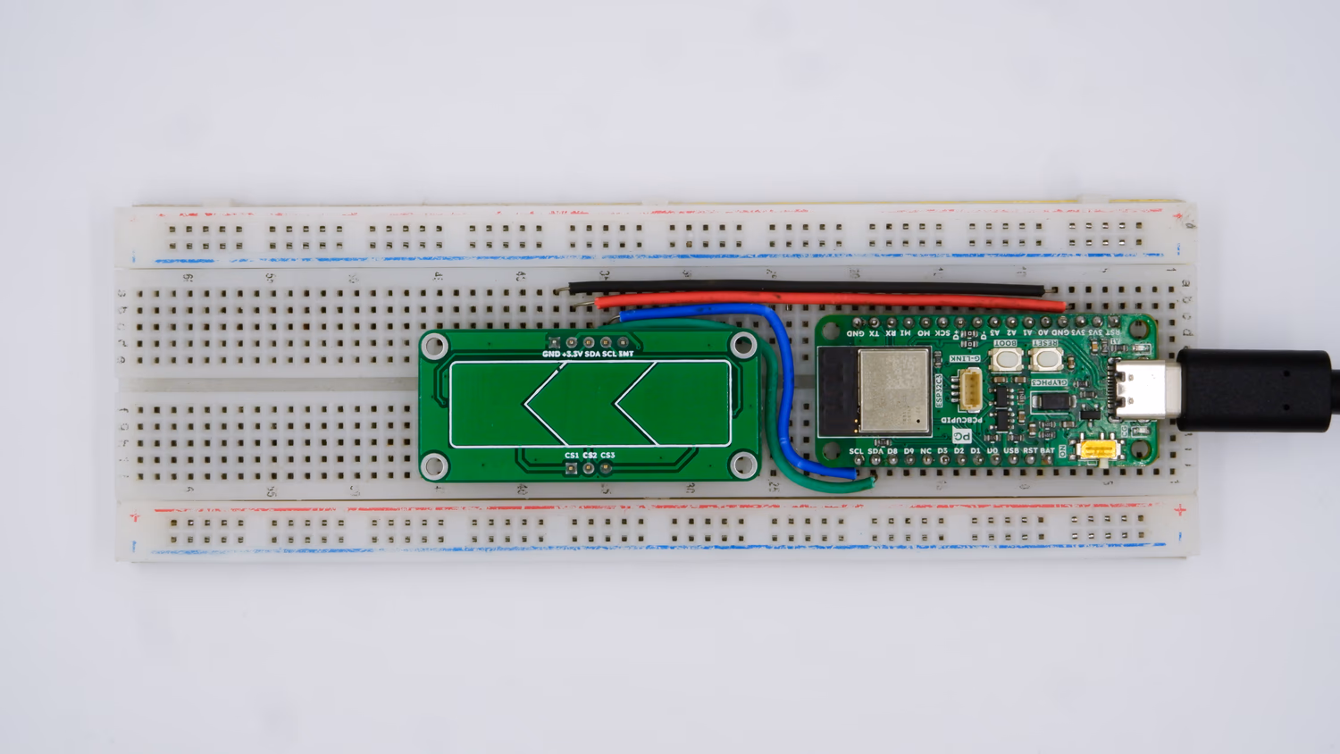
3. Through a GLINK
This method is the most convenient if you are using modules that are Glink / stemmaQT / QWIIC compatible.
4. Connect to any GPIO pin!
ESP32 boards support GPIO multiplexing, so you can use any pin as SDA, SCL but need to change this manually in the code.
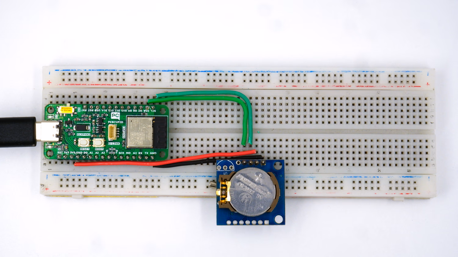
Step 1: Hardware Required
- GLYPH-C3 Board.
- Any I2C Compatible Sensor / Modules
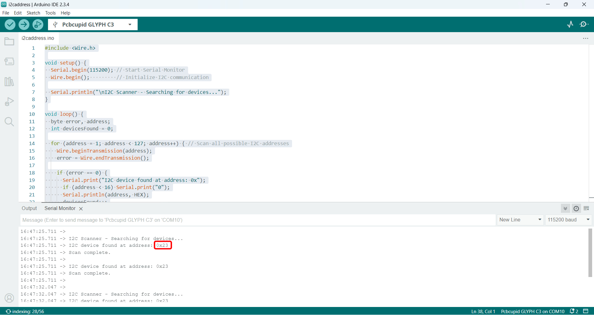
Step 2: Code Setup
- Open Arduino IDE
- Enter the following code into the Arduino IDE
Step 3: Upload the Code
- Connect the Board
- Connect your GLYPH board to your computer
-
Select the Board and Port
Do the following settings in your Arduino IDE,
Do the following settings in your Arduino IDE,
Tools > Board > esp32 > Pcbcupid GLYPH C3
For the Pcbcupid GLYPH C3 to appear under Tools > Board > esp32, the esp32 board version installed in the Arduino IDE should be greater than or equal to 3.1.0.
Tools > Port and select the port connected to your GLYPH.Tools > USB CDC on Boot > Enabled
If USB CDC on BOOT not enabled, you won’t be seeing any serial data on Arduino IDE.
- Upload the Code
- Click the upload button (➡️ icon) or use the shortcut
CTRL + U in Arduino IDE to upload the code to the board.
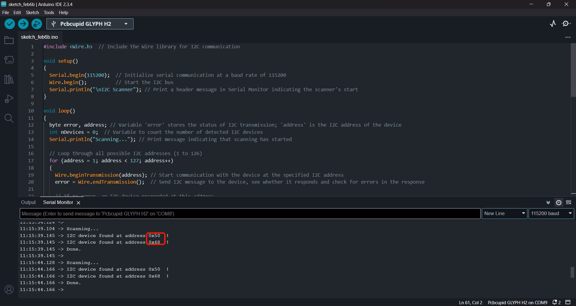
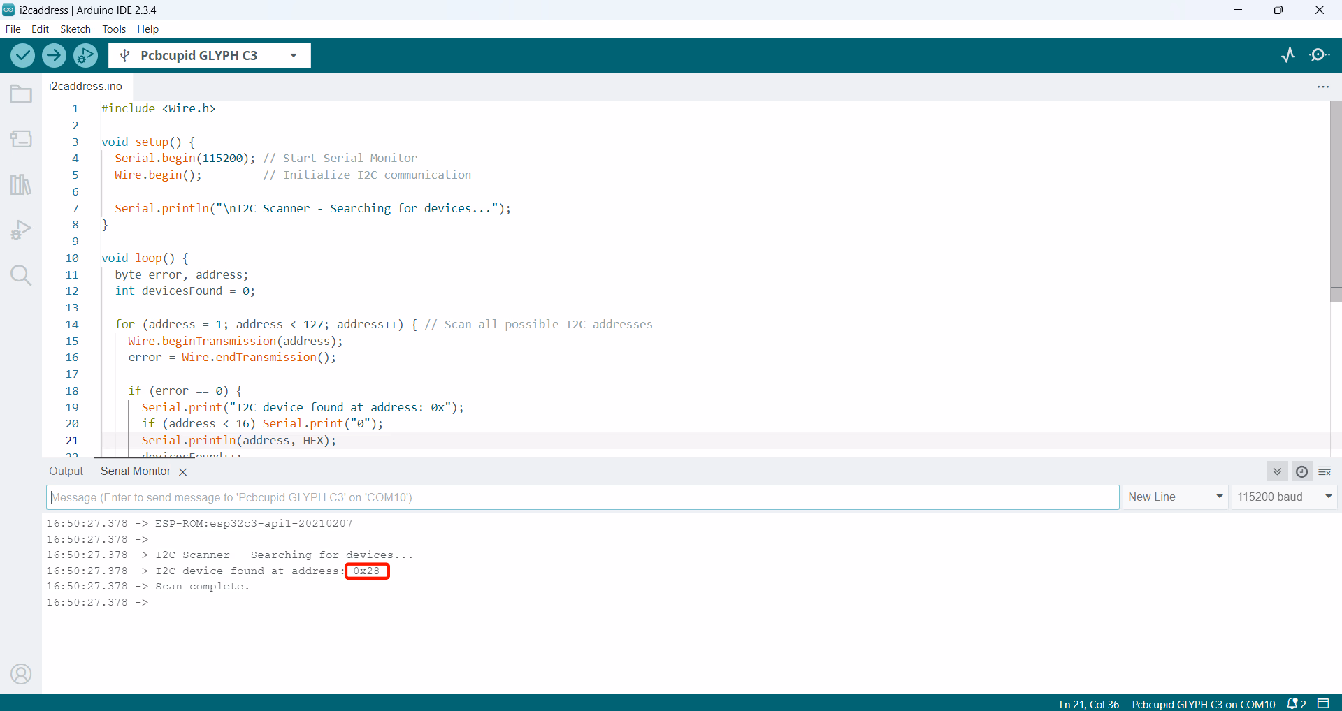
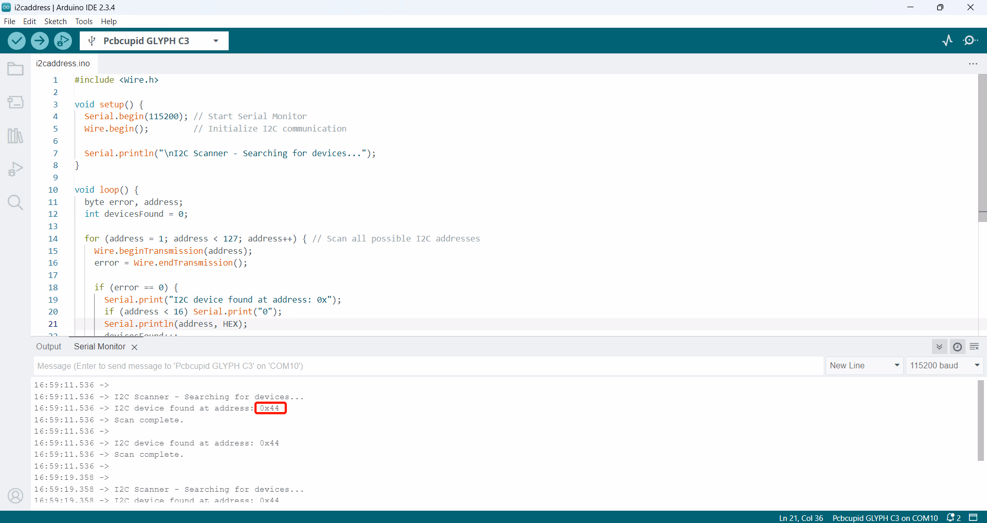
Step 4: Check Serial Monitor
The Serial Monitor should display the I2C Addresses if a device connected on the I2C bus:
GSense Capacitive Touch Slider Sensor I2C Address
 SHT 35 I2C Address
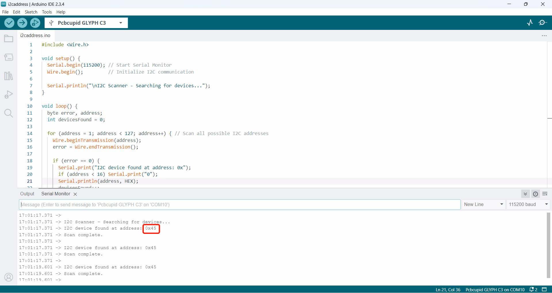 SHT 45 I2C Address
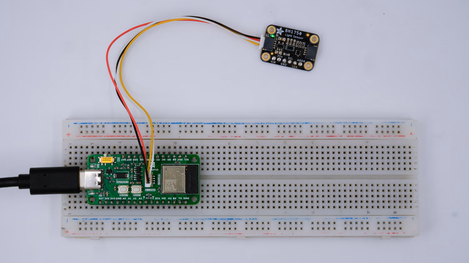
 BH1750 Adafruit Light Sensor I2C Address
 The DS1307 Module has an Onboard AT24C32 EEPROM so you would likely see 2 different I2C address.
DS1307 Real Time Clock (RTC) module I2C Address
The DS1307 Module has an Onboard AT24C32 EEPROM so you would likely see 2 different I2C address.
DS1307 Real Time Clock (RTC) module I2C Address