Integrating Adafruit with GLYPH Boards
 This guide helps you integrate the BH1750 light sensor with GLYPH Boards assuming you are using GLYPH-C3 (but any GLYPH development board from the ESP32 Series should work). Along with that it should prove to be a good example for using G-LINK that comes as a part of GLYPH board and also shows cross compatibility between G-LINK and QWIIC Connector. The provided code in this example should reads light levels and prints them to the Serial Monitor. We’ll walk you through setting up the sensor and modifying the code.
Step 1: Hardware Required
- Glyph Boards
- BH1750 light sensor
- GLINK / QWIIC connector
- Breadboard (optional)
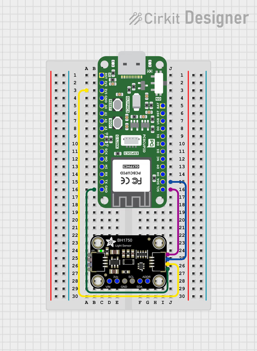
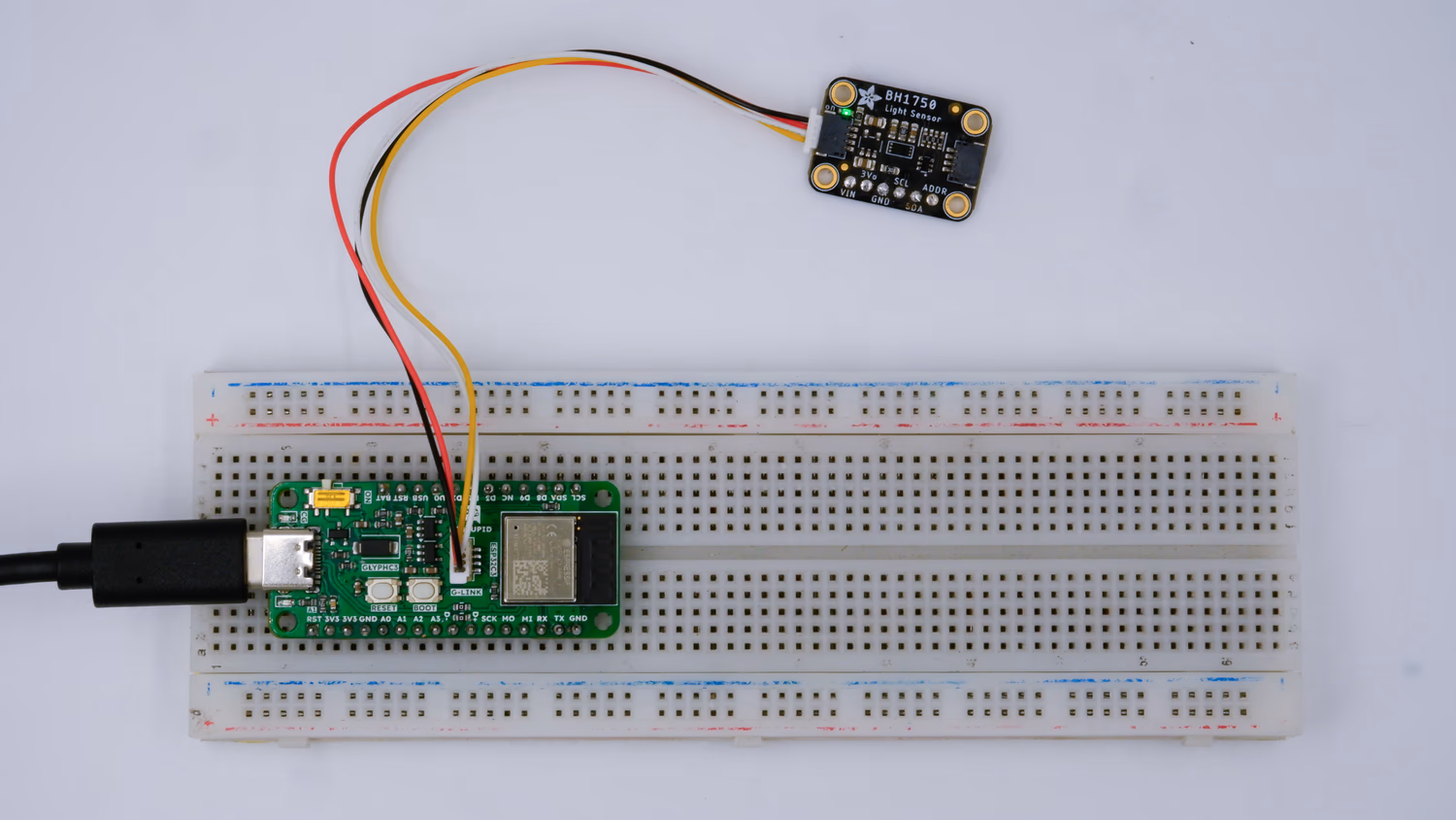
Step 2: Circuit Diagram
Connect the BH1750 sensor to the Glyph boards using the following pin configurations:
- VCC to 3.3V (on the Adafruit board)
- GND to GND
- SCL to SCL
- SDA to SDA
Step 3: Code setup
- Open Arduino IDE.
- Copy and paste the following code into the Arduino IDE:
Explanation
- Wire.begin(): On the GLYPH boards, you can use the default
Wire.begin() to initialize the I2C bus, or specify the SDA and SCL pins manually if needed.
- Sensor Setup: The
lightMeter.begin() function initializes the BH1750 sensor.
Step 4: Upload the Code
- Connect the Board
- Connect your GLYPH board to your computer
-
Select the Board and Port
Do the following settings in your Arduino IDE,
Do the following settings in your Arduino IDE,
Tools > Board > esp32 > Pcbcupid GLYPH C3
For the Pcbcupid GLYPH C3 to appear under Tools > Board > esp32, the esp32 board version installed in the Arduino IDE should be greater or equal to 3.1.0.
Tools > Port and select the port connected to your GLYPH.Tools > USB CDC on Boot > Enabled
If USB CDC on BOOT not enabled, you won’t be seeing any serial data on Arduino IDE.
- Upload the Code
- Click the upload button (➡️ icon) or use the shortcut
CTRL + U in Arduino IDE to upload the code to the board.
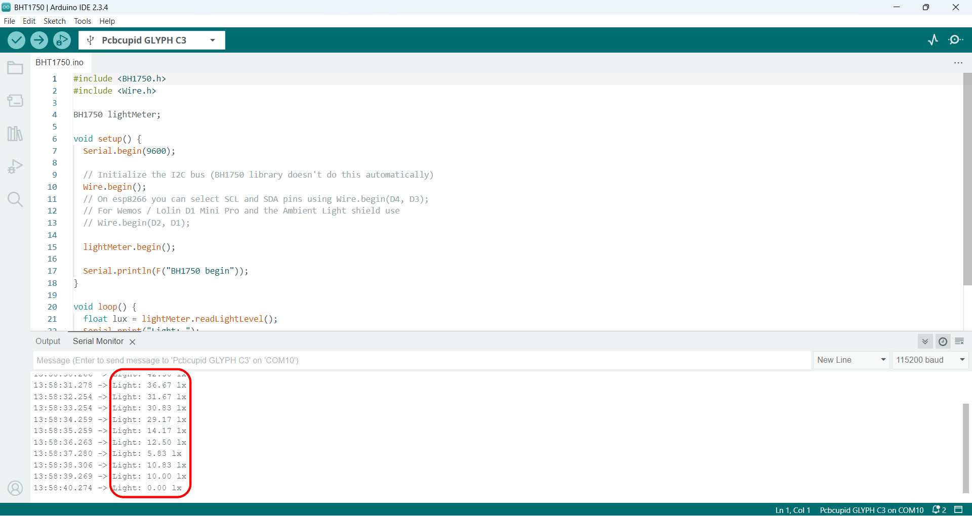
Step 5: Check the Output on Serial Monitor
-
Open the Serial Monitor
- After uploading the code, open the Serial Monitor by clicking on the magnifying glass icon in the top right corner of Arduino IDE or by going to
Tools > Serial Monitor.
-
Set the Baud Rate
- Ensure the baud rate is set to
9600.
-
Read the Light Levels
- The Serial Monitor will display light levels in lux measured by the BH1750 sensor. The output should look something like this: