Reading Analog Input / Output with GLYPH
 This guide will help you read Analog input using a Potentiometer and write it to an LED to control it’s brightness, assuming you are using GLYPH-C3 (but any GLYPH development board)
A potentiometer is a variable resistor with three terminals that adjusts voltage by sliding a wiper across a resistive track. It works as a voltage divider(A voltage divider is a simple circuit that reduces voltage using two resistors in series. It’s commonly used to step down voltages for sensors, ADC inputs, or interfacing components with different voltage levels), where the output voltage varies based on the wiper’s position.
When you move the wiper of a potentiometer (variable resistor), it changes the resistance between the wiper and the two end terminals, which in turn varies the output voltage according to the voltage divider rule.
A potentiometer works as a variable voltage divider with three terminals:
This guide will help you read Analog input using a Potentiometer and write it to an LED to control it’s brightness, assuming you are using GLYPH-C3 (but any GLYPH development board)
A potentiometer is a variable resistor with three terminals that adjusts voltage by sliding a wiper across a resistive track. It works as a voltage divider(A voltage divider is a simple circuit that reduces voltage using two resistors in series. It’s commonly used to step down voltages for sensors, ADC inputs, or interfacing components with different voltage levels), where the output voltage varies based on the wiper’s position.
When you move the wiper of a potentiometer (variable resistor), it changes the resistance between the wiper and the two end terminals, which in turn varies the output voltage according to the voltage divider rule.
A potentiometer works as a variable voltage divider with three terminals:
- Two outer terminals connect to a fixed resistance.
- The middle terminal (wiper) moves along the resistive track, changing the resistance ratio.
- As the wiper moves, the output voltage varies proportionally between the input voltage and ground.
- Analog to Digital Conversion (ADC) - This is a peripheral on the GLYPH board which is used to convert Analog signals like Voltage to Digital values. This allows GLYPH to read and process the analog signals. The Resolution on the GLYPH series boards is 12-bit (0 - 4095)
- Pulse Width Modulation (PWM) - This peripheral on the GLYPH is used to output an Analog-like signal from digital signal. This is done by modifying the Pulse-Width/Duty cycle of the digital signals generated by the GLYPH. Alternatively you can use DAC on the GLYPH but it would be complicated for beginners.
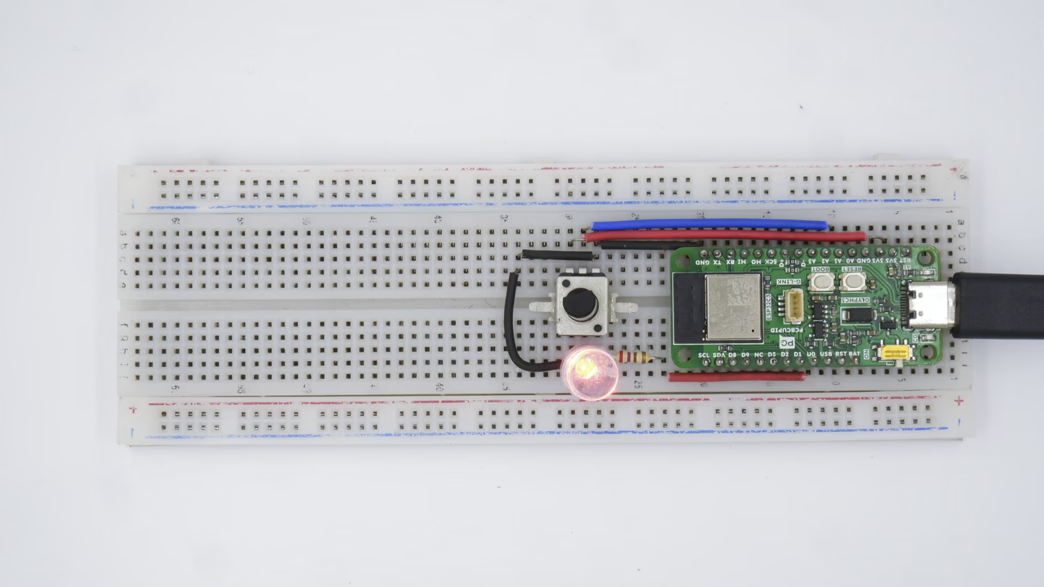
Step 1: Hardware Required
- GLYPH-C3 Board
- LED
- 220 Ohm Resistor
- Potentiometer - 47k
- Breadboard
- Male to Male Jumper Wires
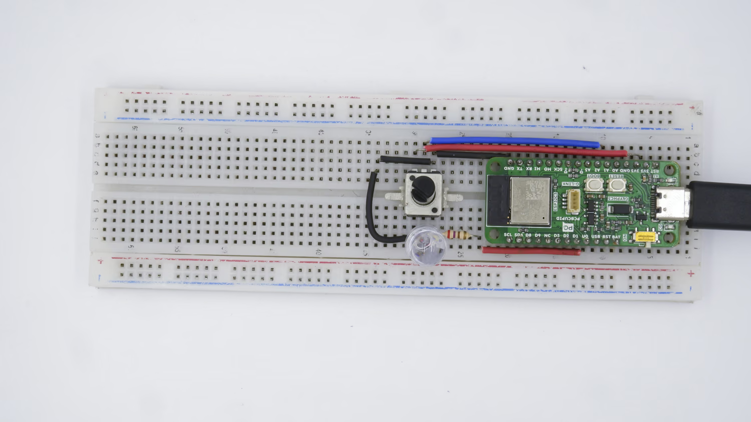
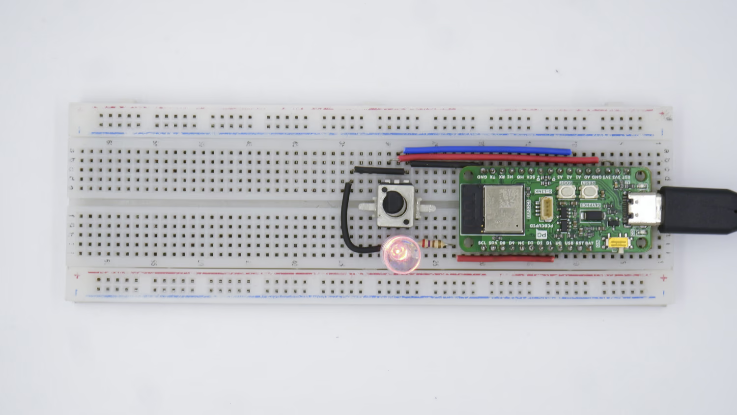
Step 2: Circuit Diagram
Connect the circuit as per the following Circuit Diagram: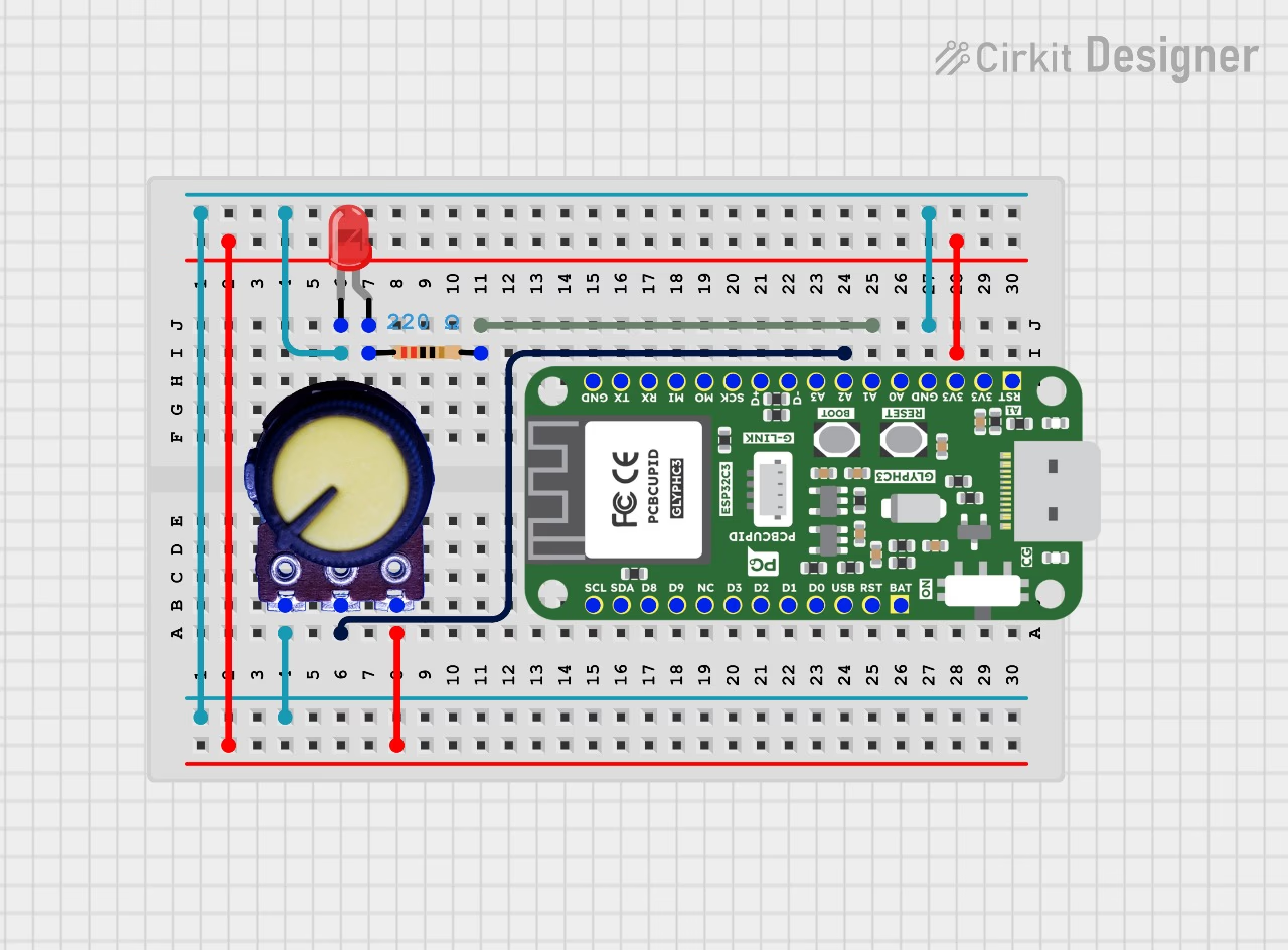
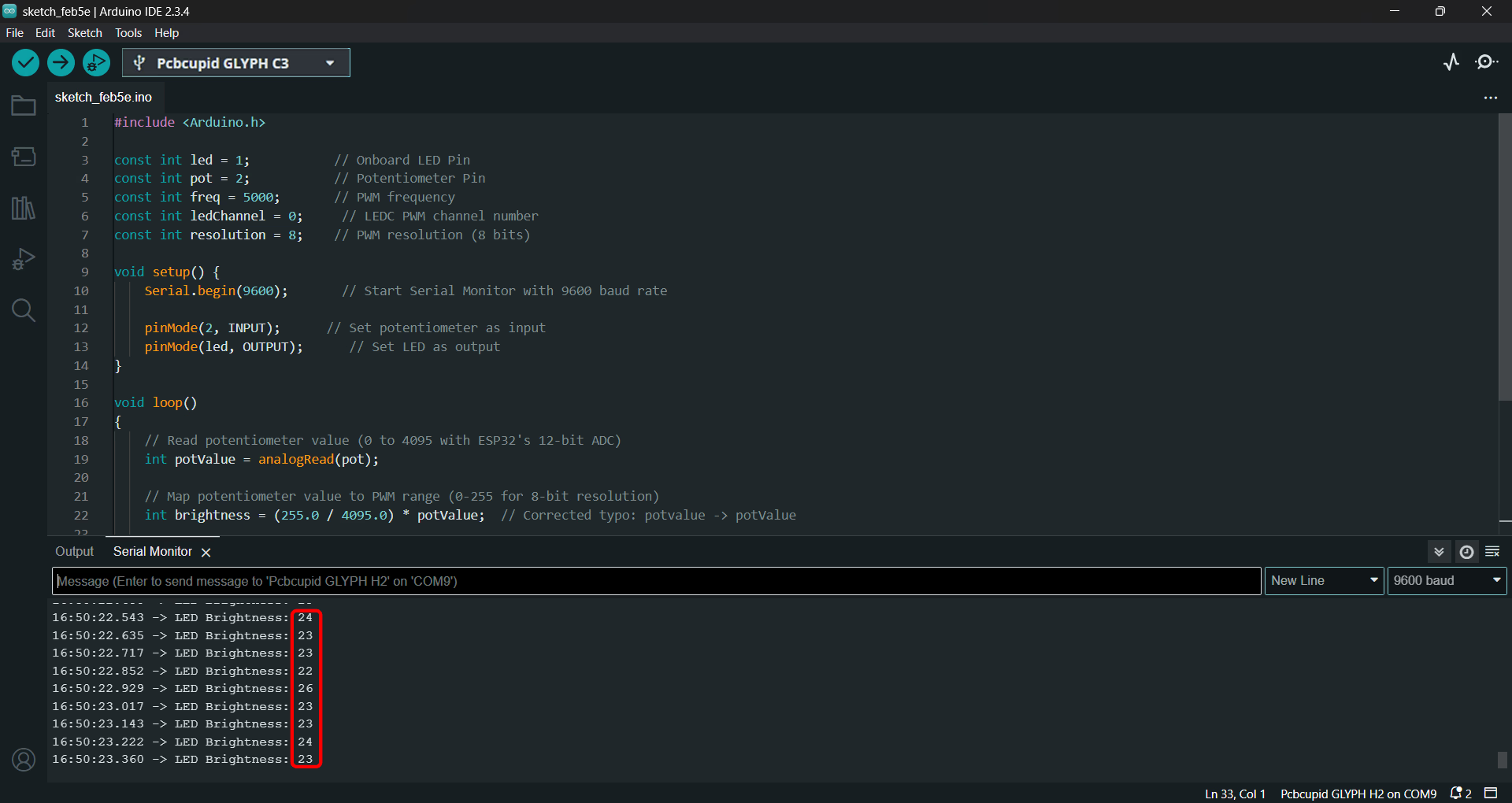
Step 3: Code Setup
In this program, the Configuring and Writing of LED PWM Value can be done in 2 Ways:- Method 1 - Using ledcWrite() function for ESP32 based GLYPH Boards
- Method 2 - Using analogWrite() function for Arduino Compatible GLYPH Boards
- Open Arduino IDE
- Enter the following code into the Arduino IDE
- Method 1 : Using ledcWrite() function
- Method 2 : Using analogWrite() function
void analogWriteResolution(uint8_t pin, uint32_t resolution bits)
void analogWriteFrequency(uint8_t pin, uint32_t freq).
Step 4: Upload the Code
- Connect the Board
- Connect your GLYPH board to your computer
-
Select the Board and Port
Do the following settings in your Arduino IDE,
Do the following settings in your Arduino IDE,
Tools > Board > esp32 > Pcbcupid GLYPH C3
Tools > Portand select the port connected to your GLYPH.Tools > USB CDC on Boot >Enabled
- Upload the Code
- Click the upload button (➡️ icon) or use the shortcut
CTRL + Uin Arduino IDE to upload the code to the board.
Step 5: Observe the Output
Depending on the Initial Position of the Potentiometer Knob, few cases are possible:- Case 1 - The LED is in OFF state
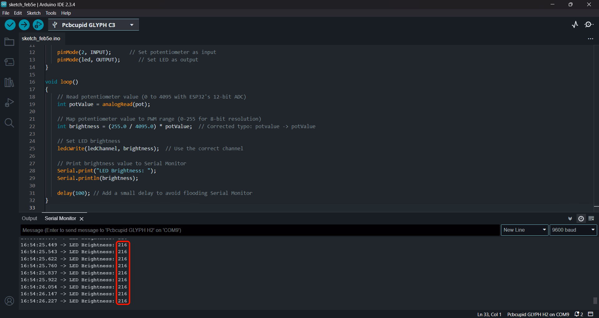
 To Turn ON the LED and increase its brightness, slowly turn the Potentiometer Knob in the Clockwise direction. At the Maximum Possible Limit of the Clockwise Rotation, the LED will glow the Brightest.The Serial Monitor should now display the Brightness value which is the Maximum PWM Duty Cycle value as 255(HIGH) or a value in the range 200-255 due to the knob-turning limitations of the potentiometer that we use.
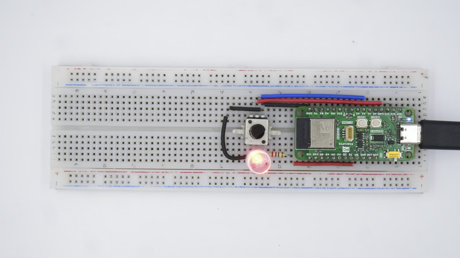
- Case 2 - The LED is in ON state
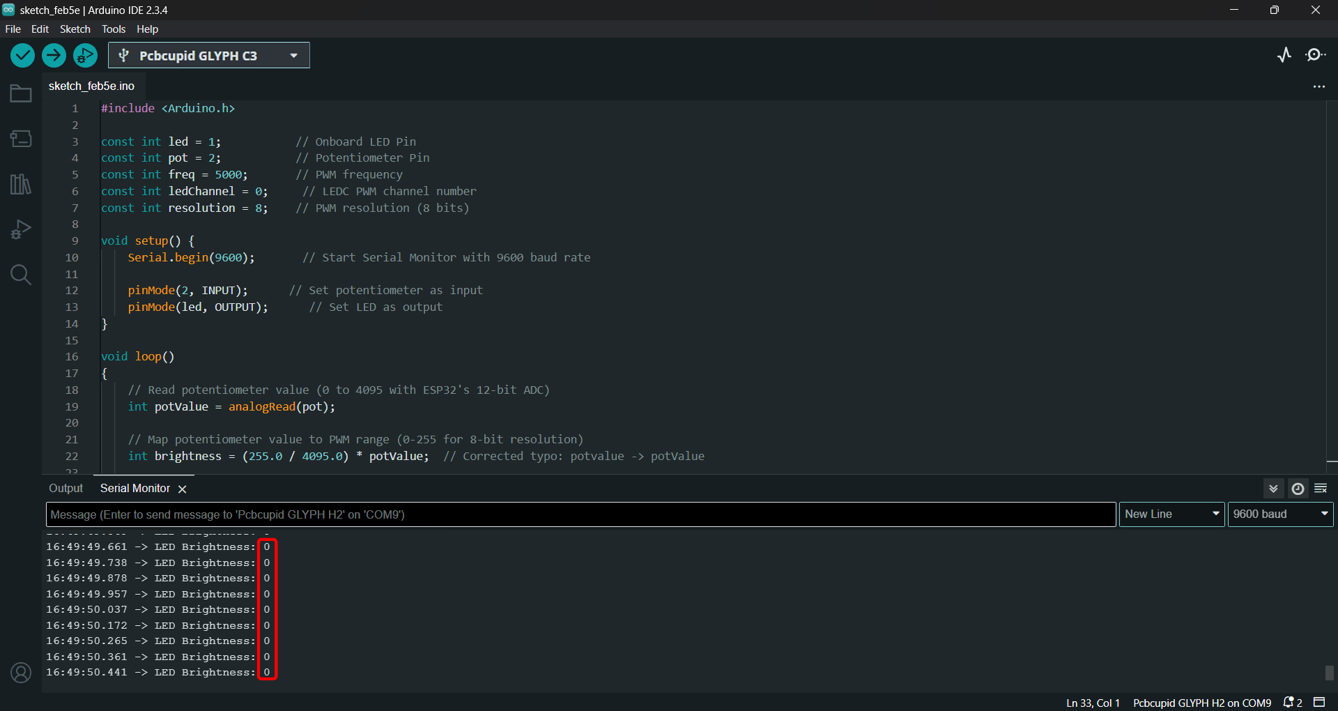
 To Turn OFF the LED and decrease its brightness, slowly turn the Potentiometer knob in the Anti-Clockwise direction. At the Maximum Possible Limit of the Anti-Clockwise Rotation, the LED will not glow at all and its brightness value will again become 0.
- Case 3 - The LED is in ON state with a Brightness value of 22(or numbers close to 22, in the range of 20-30, as an exact value of 22 may be difficult to get by manually turning your potentiometer knob).
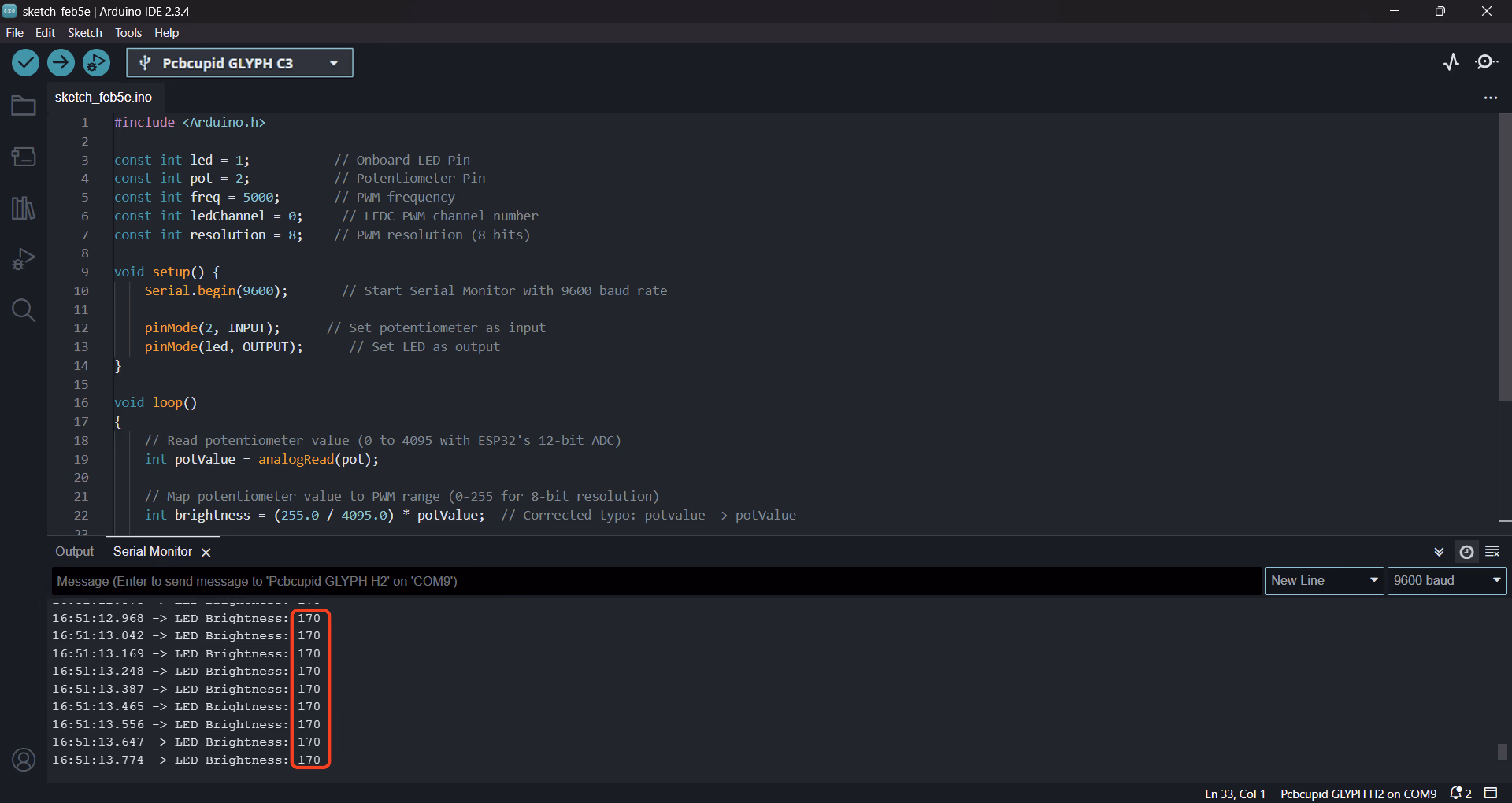
- Case 4 - The LED is in ON state with a Brightness value of 170(or numbers close to 170) The Serial Monitor should now display the value of 170 or values close to 170: