Flame Sensor Test using GLYPH-C6
An IR (Infrared) sensor is an electronic device that detects infrared radiation (IR light) emitted by objects. It typically consists of an IR emitter (like an IR LED) and an IR receiver (like a photodiode or phototransistor). IR sensors are commonly used for detecting motion, measuring distance, or sensing heat and flames, depending on the design and wavelength sensitivity. This example demonstrates how to use a flame sensor with a GLYPH-C6 (ESP32-C6) board to detect fire or flame by reading analog values and comparing them with a threshold. How it Works The flame sensor outputs an analog voltage proportional to the intensity of detected IR radiation (from fire). When the analog value drops below a preset threshold, we assume a flame is detected. Flame Emits IR Radiation- All flames release heat and IR light, usually in the range of 760–1100 nanometers (nm).
- IR Sensor Detects This Radiation The IR receiver in the sensor is tuned to pick up IR waves in that flame-specific range. When a flame is nearby, this IR light hits the sensor.
- Sensor Processes the Signal The sensor checks the intensity of the incoming IR light. If it’s strong enough, it decides a flame is present.
- Output Changes The sensor gives a signal: Digital Output (D0) becomes LOW (0V) when flame is detected. Analog Output (A0) gives a low value (0–300) when flame is nearby.
Make sure your flame sensor outputs analog voltage (some have digital-only pins). GPIO 4 on GLYPH supports analog read.
Step 1: Hardware Required
- GLYPH Board
- Flame Sensor Module (Analog output type)
- Jumper Wires
- Breadboard
- Flame or lighter for testing
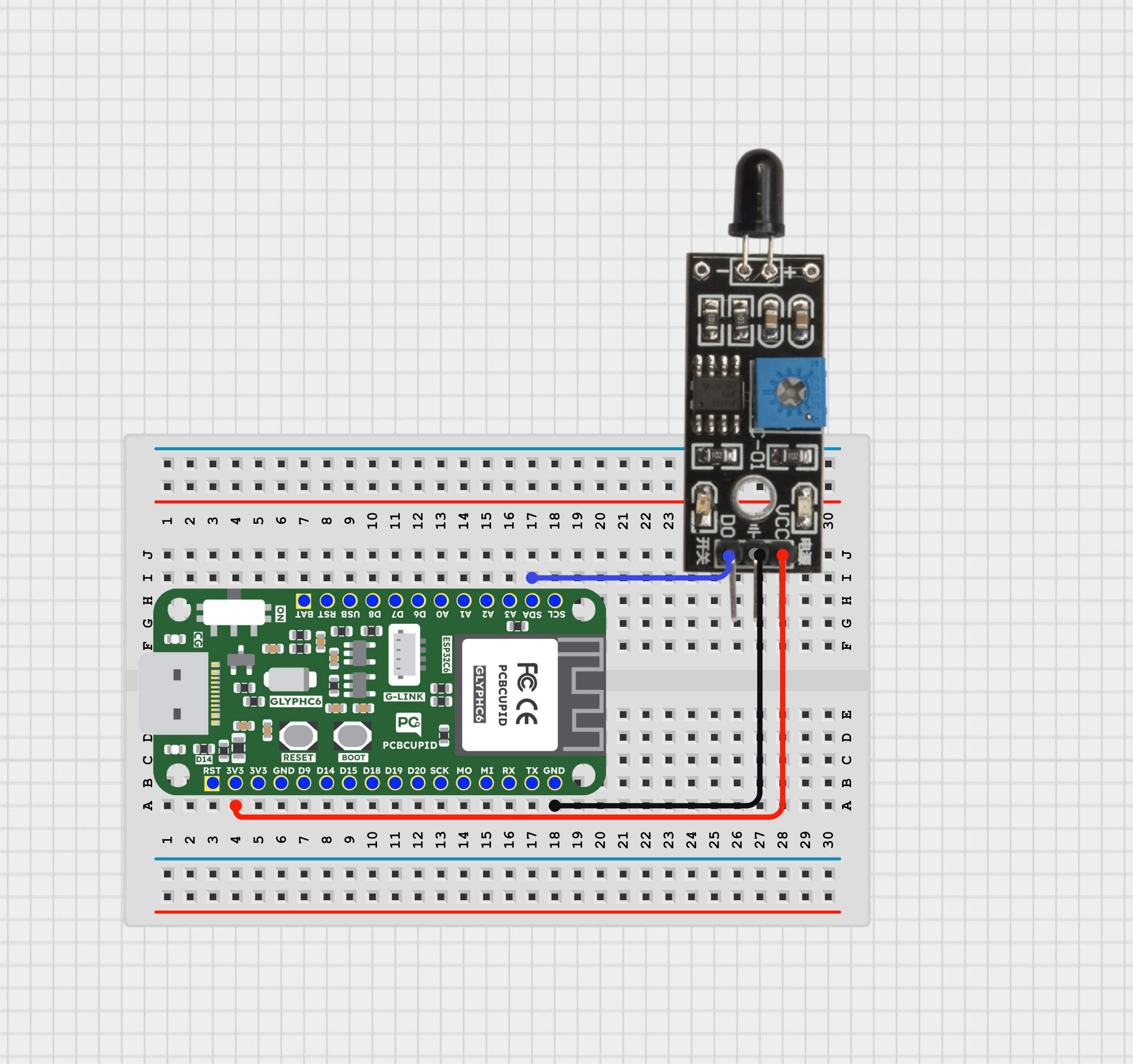
Step 2: Circuit Diagram
Flame Sensor Pinout:- D0 / A0 → Analog output
- VCC → 3.3V or 5V (based on your sensor)
- GND → Ground
- Sensor D0/A0 → GPIO 4
- Sensor VCC → 3.3V
- Sensor GND → GND
Step 3: Code Setup
Step 4: Upload the Code
- Connect the Board Connect your GLYPH-C6 board to your PC using a USB cable.
- Select the Board and Port Tools > Board > esp32 > Pcbcupid GLYPH C6 Tools > Port → Select the correct COM port Tools > USB CDC on Boot → Enabled Ensure USB CDC on BOOT is enabled. Otherwise, you won’t see serial output.
- Upload the Code Click the ➡️ Upload button or press CTRL + U to upload the sketch.
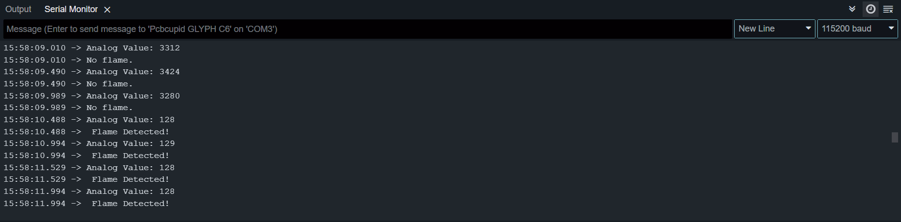
Step 5: Observe the Output on Serial Monitor
Open the Serial Monitor at 115200 baud. Without a flame nearby, the sensor shows higher analog values (e.g., ~800–1000). When you bring a flame source close to the sensor, the analog value will drop below the threshold, and the Serial Monitor will display “Flame Detected!”.