Check the back of the RTC module: modules marked “M” use the MCP79412, while those marked “P” use the PCF8563.
Pin Configuration
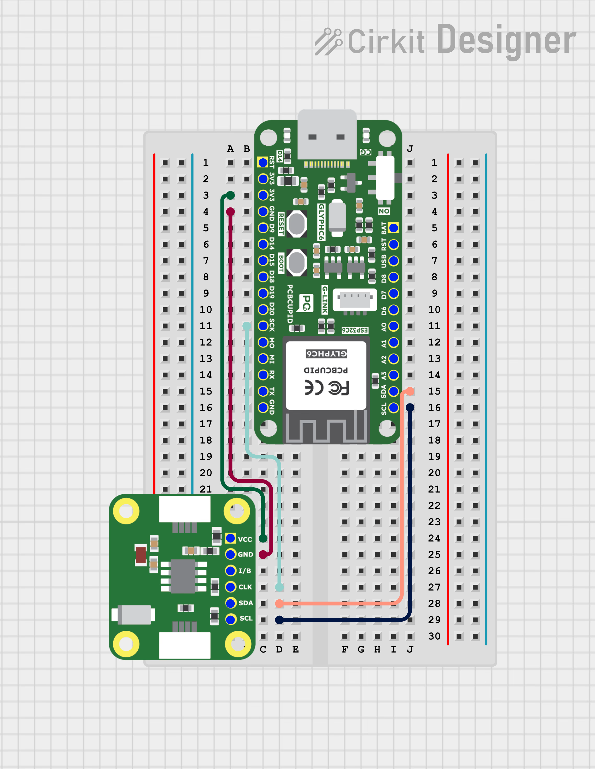
- VCC → VCC
- GND → GND
- CLK → SCK / Any GPIO
- SDA → SDA
- SCL → SCL
- B → No connection / Internally connected to the 3V battery
Install a 3V Lithium Cell (CR1220) on the RTC module to retain time when the main circuit is powered off. The module can also operate without a battery if the circuit remains powered.
Key Features
- I²C Interface (400 kHz Fast Mode)
- Timekeeping: seconds, minutes, hours, day, date, month, year with leap year compensation
- Two Alarms with programmable match options
- Battery Backup with automatic switchover
- Power-Fail Timestamp (records time of power loss)
- 64 Bytes SRAM + 1 Kbit EEPROM (non-volatile storage)
- Unique 64-bit ID (factory-programmed)
- Digital Trimming for oscillator accuracy adjustment
- Operating Voltage: 1.8V – 5.5V
- Temperature Range: −40 °C to +85 °C (industrial)
Applications
- Data loggers and metering systems
- Security and access control devices
- Consumer electronics (appliances, clocks, timers)
- Automotive time-stamping and scheduling
- Embedded systems requiring alarms, scheduling, or backup timekeeping
Step 1: Hardware Required
- Glyph Boards
- GMOD MCP79412 RTC
Step 2: Circuit Diagram
Step 3: Code Setup
- Open Arduino IDE.
- Make sure to install the library
- Copy and paste the following code into the Arduino IDE:
Step 4: Upload the Code
- Connect the Board
- Connect your GLYPH board to your computer
- Select the Board and Port
Tools > Board > esp32 > Pcbcupid GLYPH C3
Tools > Portand select the port connected to your GLYPH.Tools > USB CDC on Boot >Enabled
-
Upload the Code
- Click the upload button (➡️ icon) or use the shortcut
CRTL + Uin Arduino IDE to upload the code to the board.
- Click the upload button (➡️ icon) or use the shortcut
Step 5: Observe the Output
The RTC module tracks time independently. With the onboard 3V Lithium Cell (CR1220), it continues timekeeping even when the GLYPH is powered off.