The GMOD TB6612FNG Dual Motor Driver is a high-efficiency power control module designed to drive up to two DC motors or one bipolar stepper motor. Built around the advanced TB6612FNG dual H-bridge IC, it provides superior efficiency and lower heat generation compared to older drivers like the L298N.
This module allows for precise bidirectional control (Forward/Reverse) and speed regulation using PWM signals, making it an essential component for robotics, automated vehicles, and high-performance embedded systems.
Key Features
- Dual Channel Control: Independently drives two DC motors or one bipolar stepper motor.
- High Efficiency: MOSFET-based H-bridge design for minimal voltage drop and low heat.
- Built-in Protection: Includes over-current protection, thermal shutdown, and low-voltage detection.
- Standard Control Logic: Compatible with most microcontrollers via PWM and simple direction pins.
- Compact G-Mod Format: Plugs directly into Glyph development boards.
Technical Specifications
| Parameter | Operating Range |
|---|
| Motor Supply (VM) | 2.5V – 13.5V DC |
| Logic Supply (VCC) | 2.7V – 5.5V DC |
| Output Current | 1.2A (Continuous) / 3.2A (Peak) |
| Switching Frequency | Up to 100 kHz (PWM) |
| Internal MOSFET RDS(on) | 0.5Ω (Typical) |
Pin Configuration
The module features a standard interface for motor power and control:
| Pin Name | Description |
|---|
| VCC | Logic Logic Power (3.3V / 5V) |
| GND | Ground (Common for Logic and Power) |
| VM | External Motor Power Source (2.5V – 13.5V) |
| STBY | Standby Control (HIGH = Enable, LOW = Power Down) |
| AIN1 / AIN2 | Direction Control inputs for Motor A |
| PWMA | PWM input for Speed Control of Motor A |
| BIN1 / BIN2 | Direction Control inputs for Motor B |
| PWMB | PWM input for Speed Control of Motor B |
| AO1 / AO2 | Output terminals for Motor A |
| BO1 / BO2 | Output terminals for Motor B |
H-Bridge Control Logic
Both channels (A and B) follow the same truth table for controlling movement:
| STBY | IN1 | IN2 | PWM | Output (O1 / O2) | Motor Mode |
|---|
| LOW | X | X | X | High-Z | Standby (OFF) |
| HIGH | HIGH | LOW | HIGH | H / L | Forward |
| HIGH | LOW | HIGH | HIGH | L / H | Reverse |
| HIGH | HIGH | HIGH | X | L / L | Short Brake |
| HIGH | LOW | LOW | X | High-Z | Stop (Coast) |
Step 1: Hardware Required
- GMOD TB6612FNG Motor Driver
- GLYPH (ESP32-S3 / C3 / C6)
- 2x DC Motors
- External Battery Pack (e.g., 7.4V Li-ion or 12V LiPo)
Step 2: Circuit Connection
Connect the driver to your Glyph board following the GPIO definitions provided in your specific code example.
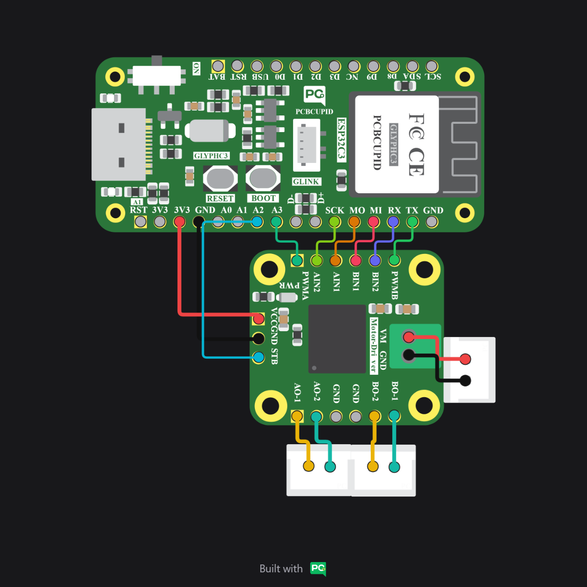
Always ensure the VM (Motor Power) and VCC (Logic Power) are not swapped, and that they share a common Ground (GND). Reversing polarity on VM can damage the TB6612FNG IC.
Step 3: Code Setup
- I2C Conflict: GPIO 5 is the default SCL pin for I2C communication across the entire GLYPH series (C3, C6, and S3). If you are using I2C sensors via the GLINK port, change the
STBY pin in the code to an alternative digital pin (e.g., GPIO 6 or 14) to avoid communication conflicts.
- Standby vs. Coast: Setting
STBY to LOW puts the driver in Standby (Power Down). For a true Coast stop where the motor spins freely, keep STBY HIGH and set both AIN1 and AIN2 to LOW.
// Mapping pins for TB6612FNG
const int STBY = 5;  // Standby pin
const int AIN1 = 18; // Motor A Direction 1
const int AIN2 = 19; // Motor A Direction 2
const int PWMA = 21; // Motor A Speed (PWM)

void setup() {
  pinMode(STBY, OUTPUT);
  pinMode(AIN1, OUTPUT);
  pinMode(AIN2, OUTPUT);
  pinMode(PWMA, OUTPUT);

  // Enable the driver
  digitalWrite(STBY, HIGH);
}

void loop() {
  // Move Forward at half speed
  digitalWrite(AIN1, HIGH);
  digitalWrite(AIN2, LOW);
  analogWrite(PWMA, 127); // Range 0-255
  delay(2000);

  // Stop (Short Brake)
  digitalWrite(AIN1, HIGH);
  digitalWrite(AIN2, HIGH);
  delay(1000);

  // Reverse at full speed
  digitalWrite(AIN1, LOW);
  digitalWrite(AIN2, HIGH);
  analogWrite(PWMA, 255);
  delay(2000);

  // Coast Stop
  digitalWrite(STBY, LOW); // Disable driver
  delay(1000);
  digitalWrite(STBY, HIGH); // Re-enable
}
Step 4: Upload the Code
-
Connect the Board
- Connect your GLYPH board to your computer via USB.
-
Select the Board and Port
In the Arduino IDE:
- Select
Tools > Board > esp32 > Pcbcupid GLYPH.
- Select
Tools > Port and choose the port connected to your board.
- Ensure
Tools > USB CDC on Boot is set to Enabled.
-
Upload
- Click the Upload button (or press
CTRL + U) to compile and flash the code.
Step 5: Observe the Output
Once the code is uploaded, the connected motors should rotate forward for 2 seconds, brake briefly, and then reverse for 2 seconds before coasting to a stop.
- STBY Pin: Remember that the STBY pin must be pulled HIGH for the motor driver to respond to any commands.
- Common Ground: Ensure the external motor power supply Ground is connected to the microcontroller Ground.
- Thermal Check: While the TB6612FNG is efficient, it may become warm when driving heavy loads. Ensure proper ventilation.