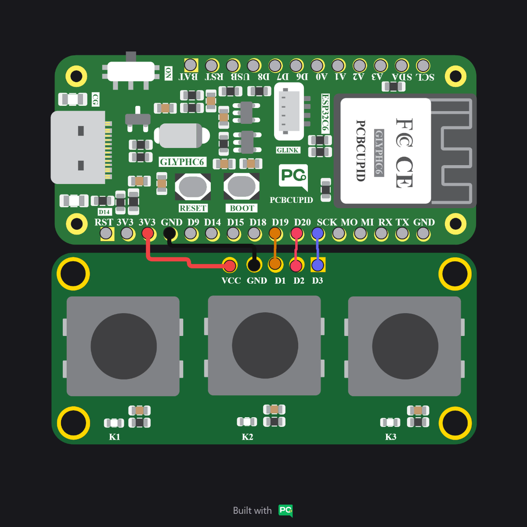
Pins Configuration
- VCC – Power supply (3.3V or 5V).
- GND – Ground.
- OUT1 – Digital signal from Button 1.
- OUT2 – Digital signal from Button 2.
- OUT3 – Digital signal from Button 3.
Key Features
- Three independent push buttons on a single module.
- Designed with clear labeling for Button 1, Button 2, Button 3.
- Each button typically connected with a pull-down/pull-up resistor (depending on design).
- Standard 4-pin/5-pin header for easy interfacing.
Applications
- Menu navigation (Up/Down/Select).
- Multi-option input control.
- Mode/Function selector in DIY electronics.
- Robotics control panels.
- Educational and prototyping projects.
Step 1: Hardware Required
- Glyph Boards
- 1×3 Push Button Module
Step 2: Circuit Diagram
Step 3: Code Setup
- Open Arduino IDE.
- Make sure to install the library
- Copy and paste the following code into the Arduino IDE:
Step 4: Upload the Code
- Connect the Board
- Connect your GLYPH board to your computer
- Select the Board and Port
Do the following settings in your Arduino IDE,
Tools > Board > esp32 > Pcbcupid GLYPH C3
- Upload the Code
- Click the upload button (➡️ icon) or use the shortcut
CRTL + Uin Arduino IDE to upload the code to the board.
- Click the upload button (➡️ icon) or use the shortcut
Step 5: Observe the Output
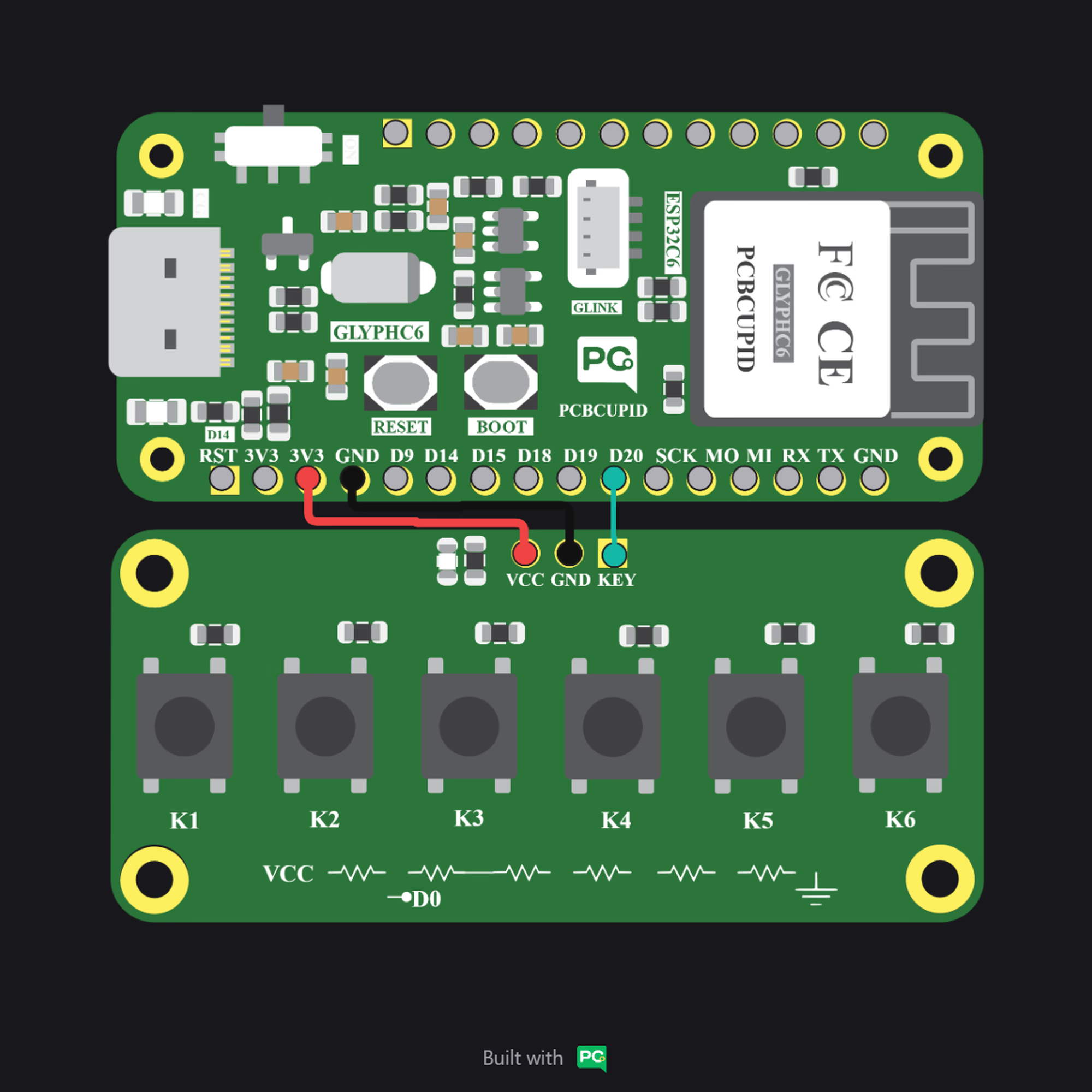
The 1×6 Key Array Module is a compact input device that integrates six tactile switches on a single board. Unlike individual digital buttons, this module uses a resistor network to generate distinct analog voltage levels for each key. When a button is pressed, the microcontroller reads a specific analog value, allowing it to identify which key was selected through a single analog input pin. This makes the module efficient for menu navigation, option selection, and multi-button control in embedded systems while minimizing the number of GPIO pins required.
Pins Configuration
- VCC - Power supply (3.3V / 5V)
- GND - Ground
- KEY (Analog Output) – Analog signal representing the pressed button
Key Features
- Six tactile switches on a single board
- Single analog output (KEY pin) for detecting all buttons
- Resistor ladder network design reduces GPIO usage
- Compatible with 3.3V and 5V microcontrollers
- Compact and easy-to-interface module
- Cost-effective solution for multi-button input systems
Applications
- Menu navigation systems
- Mode selection in embedded devices
- Human–Machine Interface (HMI) controls
- IoT device configuration panels
- DIY electronics and prototyping projects
- Educational learning kits for ADC-based input handling
Step 1: Hardware Required
- Glyph Boards
- 1×6 Push Button Module
Step 2: Circuit Diagram
Step 3: Code Setup
- Open Arduino IDE.
- Make sure to install the library
- Copy and paste the following code into the Arduino IDE:
Step 4: Upload the Code
- Connect the Board
- Connect your GLYPH board to your computer
- Select the Board and Port
Do the following settings in your Arduino IDE,
Tools > Board > esp32 > Pcbcupid GLYPH C3
- Upload the Code
- Click the upload button (➡️ icon) or use the shortcut
CRTL + Uin Arduino IDE to upload the code to the board.
- Click the upload button (➡️ icon) or use the shortcut