Check the back of the RTC module: modules marked “M” use the MCP79412, while those marked “P” use the PCF8563.
Pin Configuration
- VCC → VCC
- GND → GND
- CLK → SCK / Any GPIO
- SDA → SDA
- SCL → SCL
- I → Any GPIO / Can be used as interrupt
Key Features
- I²C (2-wire) communication interface (up to 400 kHz Fast Mode).
- Additional RTC function:
- Seconds, minutes, hours, days, weekdays, months, years.
- Automatic leap year correction (up to year 2099).
- Programmable clock output (32.768 kHz, 1 Hz, etc.).
- Two independent alarms (daily/weekly programmable).
- Countdown timer with interrupt capability.
- Ultra-low operating current (typically < 1 µA in time-keeping mode).
- Operating voltage: 1.0V – 5.5V (suitable for battery operation)
Applications
- IoT devices (timestamping sensor data).
- Clocks, watches, and portable devices.
- Data loggers.
- Industrial control and automation.
- Energy meters.
- Battery-powered embedded systems.
Step 1: Hardware Required
- Glyph Boards
- GMOD PCF8563-RTC
Step 2: Circuit Diagram

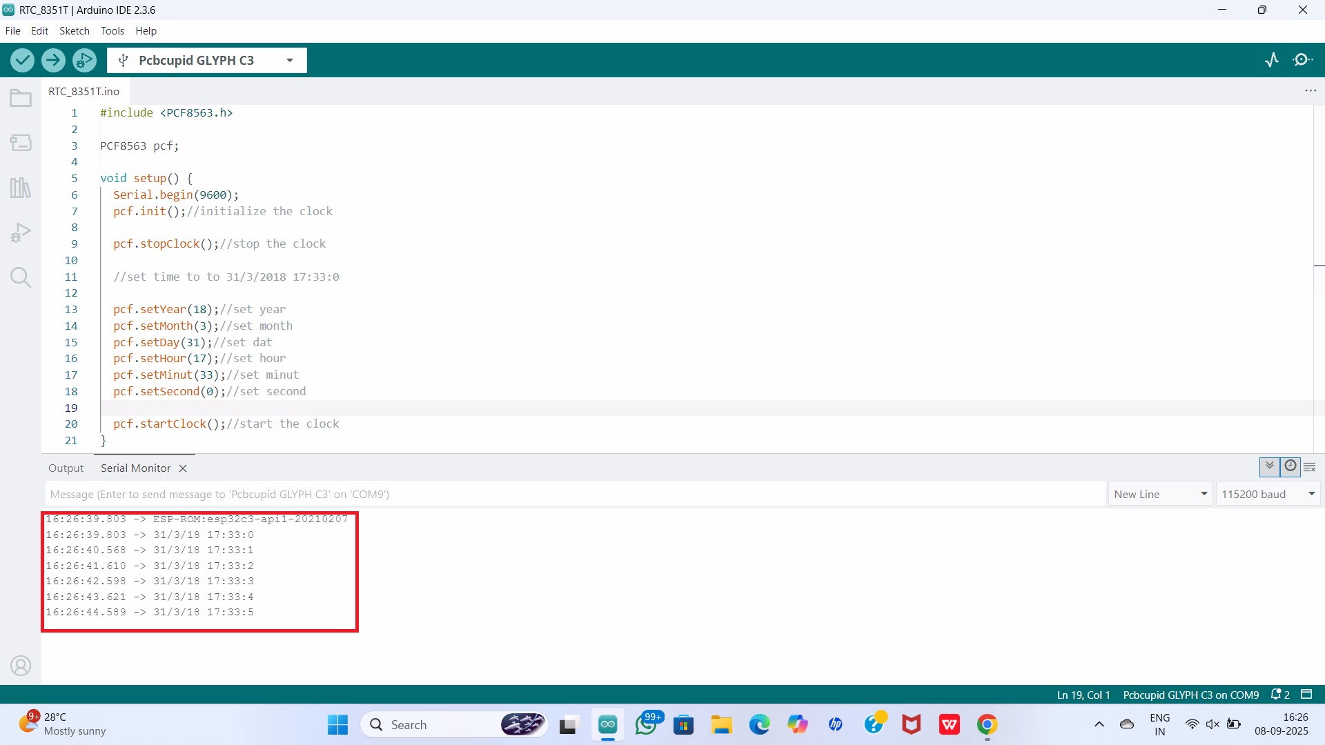
Step 3: Code Setup
- Open Arduino IDE.
- Make sure to install the library
- Copy and paste the following code into the Arduino IDE:
Step 4: Upload the Code
- Connect the Board
- Connect your GLYPH board to your computer
- Select the Board and Port
Tools > Board > esp32 > Pcbcupid GLYPH C3
Tools > Portand select the port connected to your GLYPH.Tools > USB CDC on Boot >Enabled
-
Upload the Code
- Click the upload button (➡️ icon) or use the shortcut
CRTL + Uin Arduino IDE to upload the code to the board.
- Click the upload button (➡️ icon) or use the shortcut
Step 5: Observe the Output
The RTC module tracks time independently. With the onboard 3V Lithium Cell (CR1220), it continues timekeeping even when the GLYPH is powered off.