// Load Wi-Fi library
#include <WiFi.h>

// Replace with your network credentials
const char* ssid = "your_ssid"; // Replace with your WiFi SSID
const char* password = "your_password"; // Replace with your WiFi password

// Set web server port number to 80
WiFiServer server(80); // This initializes a server object using the WiFiServer class and sets it to listen on port 80, which is the default port for HTTP. This means your Glyph C3 will host a Web Server that can handle HTTP requests on that port.

// Variable to store the HTTP request
String header; // This declares a String variable named header, which is often used in web server code to store the HTTP request header data sent by a client.

// Auxiliary variables to store the current output state
String output1State = "off";
String output2State = "off";

// Assign output variables to GPIO pins 1 & 2 (Pins A1 & A2)
const int output1 = 1;
const int output2 = 2;

// Current time
unsigned long currentTime = millis();
// Previous time
unsigned long previousTime = 0;
// Define timeout time in milliseconds (example: 2000ms = 2s)
const long timeoutTime = 2000;

void setup()
{
  Serial.begin(115200);
  // Initialize the output variables as outputs
  pinMode(output1, OUTPUT);
  pinMode(output2, OUTPUT);
  // Set outputs to LOW
  digitalWrite(output1, LOW);
  digitalWrite(output2, LOW);

  if (!WiFi.softAP(ssid, password)) {
    log_e("Soft AP creation failed.");
    while (1);
  }
  IPAddress myIP = WiFi.softAPIP();
  Serial.print("AP IP address: ");
  Serial.println(myIP);
  server.begin();

  Serial.println("Server started");
}

void loop()
{
  WiFiClient client = server.available();   // Listen for incoming clients. This is used to check for any incoming client connections to your WiFi server

  if (client) // // If a new client connects,
  {
    currentTime = millis();
    previousTime = currentTime;
    Serial.println("New Client.");          // Print a message out in the serial port
    String currentLine = "";                // Make a String to hold incoming data from the client
    while (client.connected() && currentTime - previousTime <= timeoutTime)
    {  // Loop while the client's connected
      currentTime = millis();
      if (client.available())
      {             // If there's bytes to read from the client,
        char c = client.read();             // Read a byte, then
        Serial.write(c);                    // Print it out the serial monitor
        header += c;
        if (c == '\n')
        {                    // If the byte is a newline character
          // If the current line is blank, you got two newline characters in a row.
          // That's the end of the client HTTP request, so send a response:
          if (currentLine.length() == 0)
          {
            // HTTP headers always start with a response code (e.g. HTTP/1.1 200 OK)
            // and a content-type so the client knows what's coming, then a blank line:
            client.println("HTTP/1.1 200 OK");
            client.println("Content-type:text/html");
            client.println("Connection: close");
            client.println();

            // Turn the GPIOs on and off
            if (header.indexOf("GET /1/on") >= 0) // The header.indexOf("GET /1/on") function searches the header string for the substring "GET /1/on". If this substring is found, indexOf returns the position (index) of the first occurrence. If it is not found, it returns -1.
            {
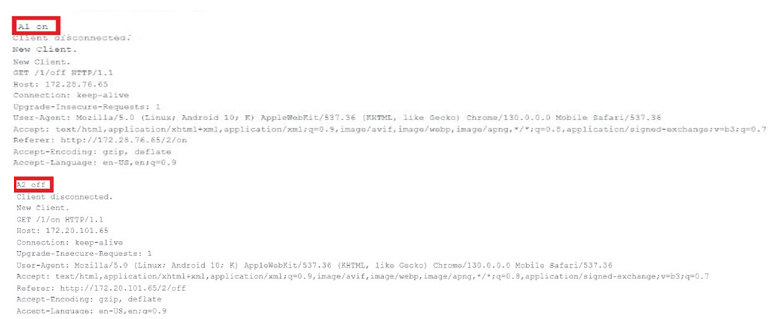
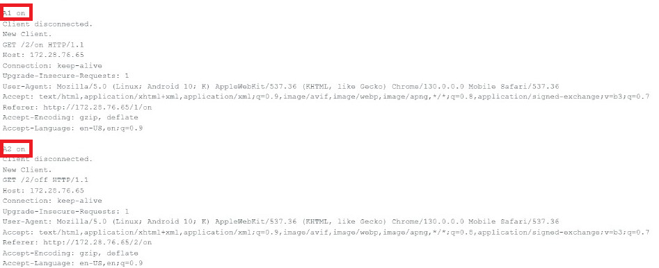
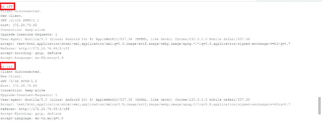
              Serial.println("A1 on"); // sends the message "A1 on" to the Serial Monitor. This line is useful for debugging, as it confirms that the code segment responsible for turning on device A1 (connected to output1) has been executed.

              output1State = "on"; // sets a variable output1State (which should be declared earlier in your code, likely as a String type) to the value "on"
              digitalWrite(output1, HIGH); // Turns on the 1st LED - A1

            }
            else if (header.indexOf("GET /1/off") >= 0)
            {
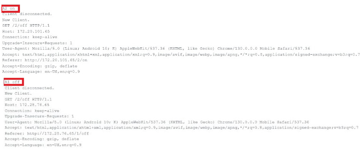
              Serial.println("A1 off"); // Print to Serial Monitor for debugging
              output1State = "off";
              digitalWrite(output1, LOW); // Turns off the 1st LED - A1
            }
            else if (header.indexOf("GET /2/on") >= 0) // "GET /2/on" is found in the header. It indicates that a client has requested to turn on a device associated with the identifier /2.
            {
              Serial.println("A2 on"); // ");// Prints a message to the Serial Monitor for debugging
              output2State = "on"; // Updates the state variable to indicate that 2nd LED - A2 is on.
              digitalWrite(output2, HIGH); // Turns on the 2nd LED - A2
            }
            else if (header.indexOf("GET /2/off") >= 0) // Checks if the command to turn on 2nd LED - A2 was received.
            {
              Serial.println("A2 off"); // Prints a message indicating that device 2 has been turned off.
              output2State = "off"; // Updates the state variable to indicate that 2nd LED - A2 is off.
              digitalWrite(output2, LOW); // Turns off the 2nd LED - A2.
            }

            // Display the HTML web page
            client.println("<!DOCTYPE html><html>"); // This line indicates that the document is HTML5. It helps the browser understand how to render the page correctly.
            client.println("<head><meta name=\"viewport\" content=\"width=device-width, initial-scale=1\">"); // This line includes a <meta> tag that sets the viewport to make the page responsive on mobile devices. The width=device-width ensures that the page scales appropriately to the device's screen size.
            client.println("<link rel=\"icon\" href=\"data:,\">"); // This line sets a blank favicon for the webpage. A favicon is the small icon shown in browser tabs. Here, an empty data URL is used, which means no icon will be displayed.
            // CSS to style the on/off buttons
            // Feel free to change the background-color and font-size attributes to fit your preferences
            client.println("<style>html { font-family: Helvetica; display: inline-block; margin: 0px auto; text-align: center;}"); // font-family: Helvetica; - Sets the font for the entire document to Helvetica, giving a clean and modern look. display: inline-block; - This allows the element to be treated as an inline element while still allowing height and width to be set.margin: 0px auto; - Centers the content on the page horizontally. The 0px vertical margin removes any default spacing above and below. text-align: center; - Centers the text within the element
            client.println(".button { background-color: #4CAF50; border: none; color: white; padding: 16px 40px;");
            client.println("text-decoration: none; font-size: 30px; margin: 2px; cursor: pointer;}");
            client.println(".button2 {background-color: #555555;}</style></head>"); // background-color: #555555;: Sets a darker gray background color for a secondary button style, which is often used for actions like "Off" or "Cancel".

            // Web Page Heading
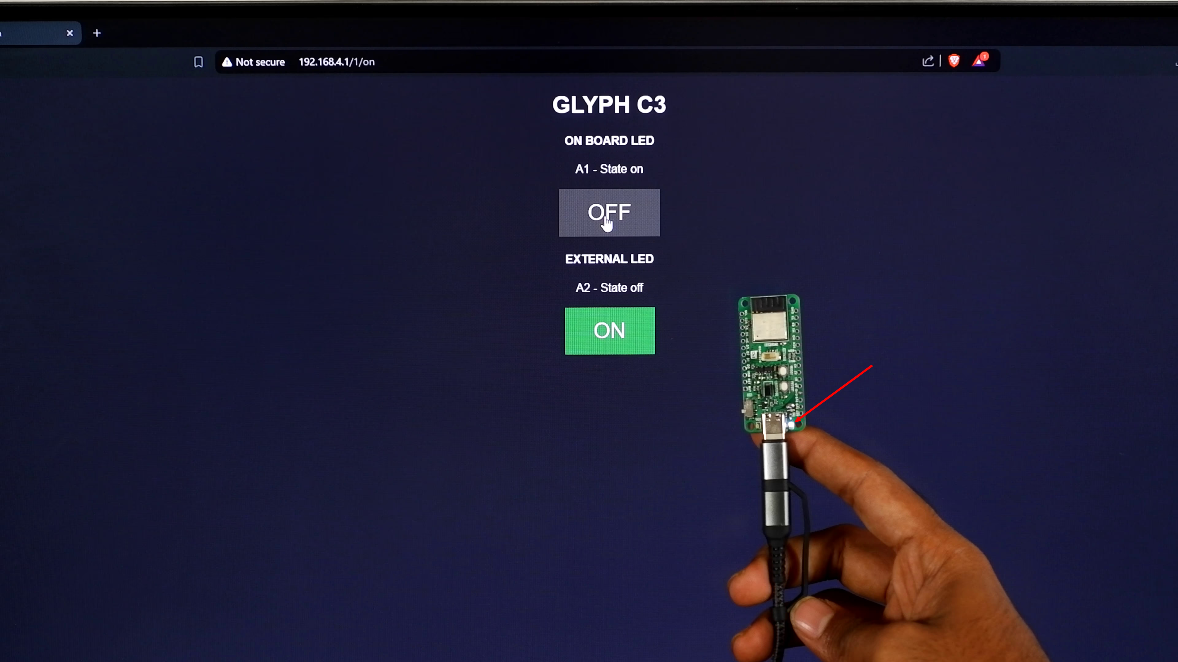
            client.println("<body><h1>GLYPH C3</h1>"); // used to add content to the HTML document being served by your Glyph C3 web server.

            // Display current state, and ON/OFF buttons for A1
            client.println("<body><h4>ON BOARD LED</h4>"); // <h4> - This tag creates a subheading. Using <h4> indicates that it's a lower-level heading compared to <h1>, which is used for the main title. This helps organize the information visually and hierarchically. ON BOARD LED - The text displayed in the subheading, indicating the section related to the on-board LED.
            client.println("<p>A1 - State " + output1State + "</p>");  // <p> - This tag defines a paragraph of text. A1 - State + output1State: This line concatenates a string to indicate the state of the LED connected to output1. The variable output1State contains the current state ("on" or "off"). This allows the web page to show whether the LED is currently on or off.

            // If the output1State is off, it displays the ON button
            if (output1State=="off")
            {
              client.println("<p><a href=\"/1/on\"><button class=\"button\">ON</button></a></p>");
            }
            else
            {
              client.println("<p><a href=\"/1/off\"><button class=\"button button2\">OFF</button></a></p>");
            }

            // Display current state, and ON/OFF buttons for A2
            client.println("<body><h4>EXTERNAL LED</h4>"); // used to generate a subheading in the HTML document that your Glyph C3 web server is serving to the client (typically a web browser)

            client.println("<p>A2 - State " + output2State + "</p>");
            // If the output2State is off, it displays the ON button
            if (output2State=="off") // This condition checks if the 2nd LED - A2 is currently off.

            {
              client.println("<p><a href=\"/2/on\"><button class=\"button\">ON</button></a></p>");
            }
            else
            {
              client.println("<p><a href=\"/2/off\"><button class=\"button button2\">OFF</button></a></p>"); // <p> - This paragraph tag creates a block for the button, ensuring proper spacing and layout in the HTML. <a href=\"/2/off\"> - This creates a hyperlink that, when clicked, sends a GET request to the server at the /2/off endpoint. This endpoint is intended to turn off the 2nd LED - A2. <button class=\"button button2\">OFF</button> - This defines a button with two classes applied: .button - Applies the general button styling defined earlier in your CSS. .button2 - Applies the secondary button style, which typically has a different background color (dark gray in your case).

            }
            client.println("</body></html>"); // Used to properly close the HTML document that you are sending to the client (web browser) from your Glyph C3 web server

            // The HTTP response ends with another blank line
            client.println();

            // Break out of the while loop
            break; // break statement is often used to exit a case of a switch statement that handles different types of requests (like GET, POST, etc.) or to exit a loop that checks for client connections or requests
          }
          else
          { // If you got a newline, then clear currentLine
            currentLine = "";
          }
        }
        else if (c != '\r')
        {  // If you got anything else but a carriage return character,
          currentLine += c;      // Add it to the end of the currentLine
        }
      }
    }
    // Clear the header variable
    header = "";
    // Close the connection
    client.stop(); // This function call closes the connection with the client. It is essential to properly close the connection after handling the request to free up resources and prevent memory leaks. This ensures that the Glyph-C3 is ready to accept new client connections.

    Serial.println("Client disconnected."); // Print that the client has been successfully disconnected.

    Serial.println("");
  }
}