Dual-Channel Relay To Switch Via WiFi
A dual-channel relay is an electromagnetic switch module with two independent relays, allowing control of two electrical devices separately using a microcontroller like GLYPH boards.
How Relay Works: You can check this link to see how the GMOD-2-CH-Relay Works!
Unlike other relay module GMOD 2-ch-Relay is HIGH level logic module, i.e :
- LOW (0V) → Relay OFF (bulb turns OFF)
- HIGH (3.3V) → Relay ON (bulb turns ON)
How relay works with on/off bulbs
- The glyph board sets up a WiFi Access Point (AP) or connects to an existing WiFi network.
- A web server runs on the glyphc3, providing buttons to toggle the relay.
- When a user clicks a button, the glyphc3 activates or deactivates the relays, switching the bulbs ON or OFF.

The GLYPH-C3 board is configured as a WiFi server, allowing users to access a web-based interface from any connected device. The 2-channel relay acts as an electrically isolated switch to turn the bulbs on and off according to user inputs received over WiFi.
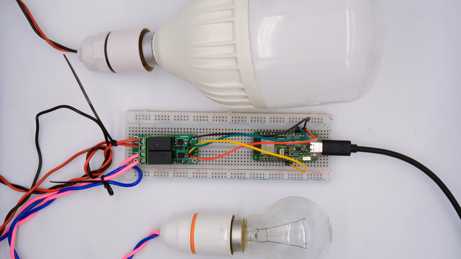
Step 1: Hardware Required
- GLYPH-C3 board (other glyph development boards too)
- GMOD Double Channel Relay Module
- 2 AC Bulbs
- Jumper Wires
Step 2: Circuit Diagram
GMOD Wiring:

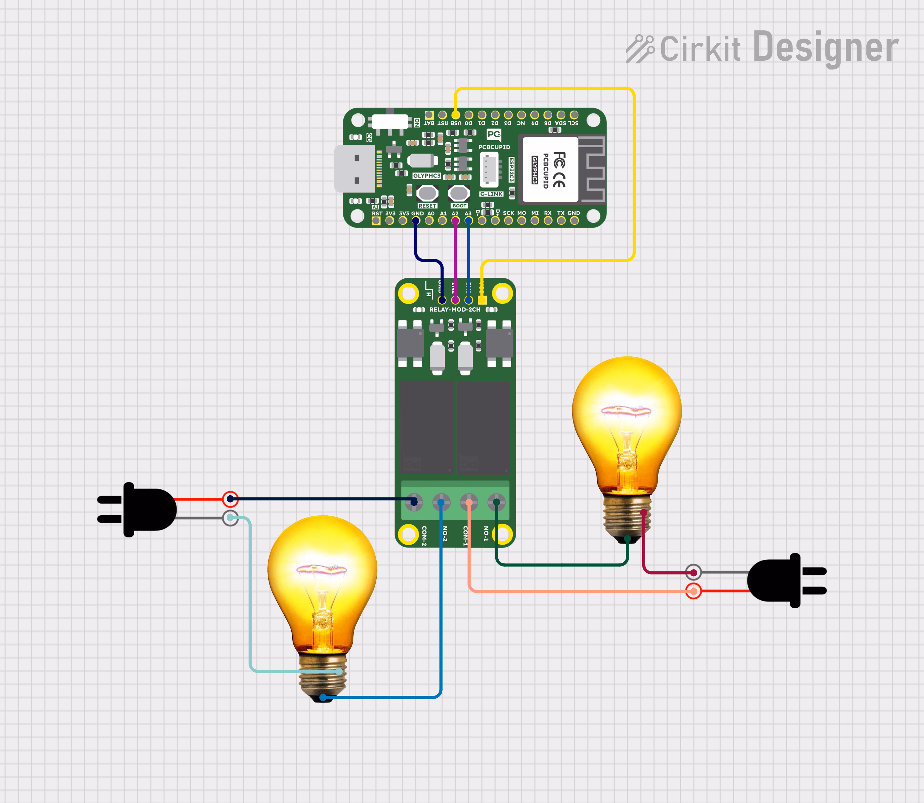
- Relay 1 IN → A2 (GLYPH)
- Relay 2 IN → A1 (GLYPH)
- VCC → 5V (GLYPH)
- GND → GND (GLYPH)
- Bulbs: Connected to relay outputs with an AC power source.
Step 3: Code Setup
- Open Arduino IDE.
- Copy and paste the following code into the Arduino IDE:
#include <WiFi.h> // Include the WiFi library for ESP32
// WiFi Credentials (Replace with your actual SSID and Password)
const char* ssid = "your_ssid"; // Your WiFi network name
const char* password = "your_password"; // Your WiFi password
WiFiServer server(80); // Create a web server on port 80 (HTTP)
// Define Relay Control Pins (Ensure GPIOs are compatible with your relay module)
#define RELAY1 A2 // connected to Relay 1 (Bulb 1)
#define RELAY2 A3 // connected to Relay 2 (Bulb 2)
void setup() {
Serial.begin(115200); // Start serial communication for debugging
delay(1000); // Short delay for stability
pinMode(RELAY1, OUTPUT); // Set relay 1 pin as output
pinMode(RELAY2, OUTPUT); // Set relay 2 pin as output
// Set relays to LOW (OFF) initially
digitalWrite(RELAY1, LOW);
digitalWrite(RELAY2, LOW);
// Connect to WiFi
Serial.println("Connecting to WiFi...");
WiFi.begin(ssid, password);
// Wait until WiFi is connected
while (WiFi.status() != WL_CONNECTED) {
delay(500);
Serial.print(".");
}
// Print IP address assigned to ESP32
Serial.println("\nWiFi Connected!");
Serial.print("IP Address: ");
Serial.println(WiFi.localIP());
server.begin(); // Start the web server
}
void loop() {
WiFiClient client = server.available(); // Check if a client has connected
if (client) { // If a client is connected
Serial.println("\nClient Connected");
String request = client.readStringUntil('\r'); // Read the HTTP request
Serial.print("Received Request: ");
Serial.println(request);
client.flush(); // Clear the request buffer
// Control Relays Based on the Request URL
if (request.indexOf("/bulb1on") != -1) {
digitalWrite(RELAY1, HIGH); // Turn ON Relay 1 (Bulb 1)
Serial.println("Bulb 1 TURNED ON");
}
else if (request.indexOf("/bulb1off") != -1) {
digitalWrite(RELAY1, LOW); // Turn OFF Relay 1 (Bulb 1)
Serial.println("Bulb 1 TURNED OFF");
}
else if (request.indexOf("/bulb2on") != -1) {
digitalWrite(RELAY2, HIGH); // Turn ON Relay 2 (Bulb 2)
Serial.println("Bulb 2 TURNED ON");
}
else if (request.indexOf("/bulb2off") != -1) {
digitalWrite(RELAY2, LOW); // Turn OFF Relay 2 (Bulb 2)
Serial.println("Bulb 2 TURNED OFF");
}
else if (request.indexOf("/bothon") != -1) {
digitalWrite(RELAY1, HIGH);
digitalWrite(RELAY2, HIGH); // Turn ON both bulbs
Serial.println("BOTH BULBS TURNED ON");
}
else if (request.indexOf("/bothoff") != -1) {
digitalWrite(RELAY1, LOW);
digitalWrite(RELAY2, LOW); // Turn OFF both bulbs
Serial.println("BOTH BULBS TURNED OFF");
}
else if (request.indexOf("/bulb1on2off") != -1) {
digitalWrite(RELAY1, HIGH); // Bulb 1 ON
digitalWrite(RELAY2, LOW); // Bulb 2 OFF
Serial.println("Bulb 1 TURNED ON, Bulb 2 TURNED OFF");
}
else if (request.indexOf("/bulb2on1off") != -1) {
digitalWrite(RELAY1, LOW); // Bulb 1 OFF
digitalWrite(RELAY2, HIGH); // Bulb 2 ON
Serial.println("Bulb 2 TURNED ON, Bulb 1 TURNED OFF");
}
// Respond to Client with Web Interface
client.println("HTTP/1.1 200 OK"); // Send HTTP response header
client.println("Content-Type: text/html"); // Specify HTML content
client.println();
// Start HTML Content
client.println("<!DOCTYPE html><html><head>");
client.println("<title>WiFi Bulb Control</title>");
// Basic CSS for button styling
client.println("<style>");
client.println("body { font-family: Arial; text-align: center; background-color: #f8f9fa; }");
client.println(".button { display: inline-block; padding: 15px 30px; margin: 10px; font-size: 20px; color: white; border: none; cursor: pointer; border-radius: 10px; text-decoration: none; }");
client.println(".on { background-color: #28a745; }"); // Green button for ON
client.println(".off { background-color: #dc3545; }"); // Red button for OFF
client.println(".both { background-color: #007bff; }"); // Blue button for Both
client.println("</style>");
client.println("</head><body>");
client.println("<h2>WiFi Bulb Control</h2>");
// Buttons for controlling Bulb 1
client.println("<a class='button on' href='/bulb1on'>Bulb 1 ON</a>");
client.println("<a class='button off' href='/bulb1off'>Bulb 1 OFF</a>");
client.println("<br>");
// Buttons for controlling Bulb 2
client.println("<a class='button on' href='/bulb2on'>Bulb 2 ON</a>");
client.println("<a class='button off' href='/bulb2off'>Bulb 2 OFF</a>");
client.println("<br>");
// Buttons for controlling both bulbs at the same time
client.println("<a class='button both' href='/bothon'>Both ON</a>");
client.println("<a class='button both' href='/bothoff'>Both OFF</a>");
client.println("<br>");
// Buttons for alternate ON/OFF configurations
client.println("<a class='button on' href='/bulb1on2off'>Bulb 1 ON, Bulb 2 OFF</a>");
client.println("<a class='button on' href='/bulb2on1off'>Bulb 2 ON, Bulb 1 OFF</a>");
client.println("</body></html>"); // Close HTML content
client.stop(); // Disconnect client
}
}
Step 4: Upload the Code
- Connect the Board
- Connect your GLYPH board to your computer
-
Select the Board and Port
Do the following settings in your Arduino IDE, Do the following settings in your Arduino IDE,
Tools > Board > esp32 > Pcbcupid GLYPH C3
For the Pcbcupid GLYPH C3 to appear under Tools > Board > esp32, the esp32 board version installed in the Arduino IDE should be greater than or equal to 3.1.0.
Tools > Portand select the port connected to your GLYPH.Tools > USB CDC on Boot >Enabled
If USB CDC on BOOT not enabled, you won't be seeing any serial data on Arduino IDE.
- Upload the Code
- Click the upload button (➡️ icon) or use the shortcut
CTRL + Uin Arduino IDE to upload the code to the board.
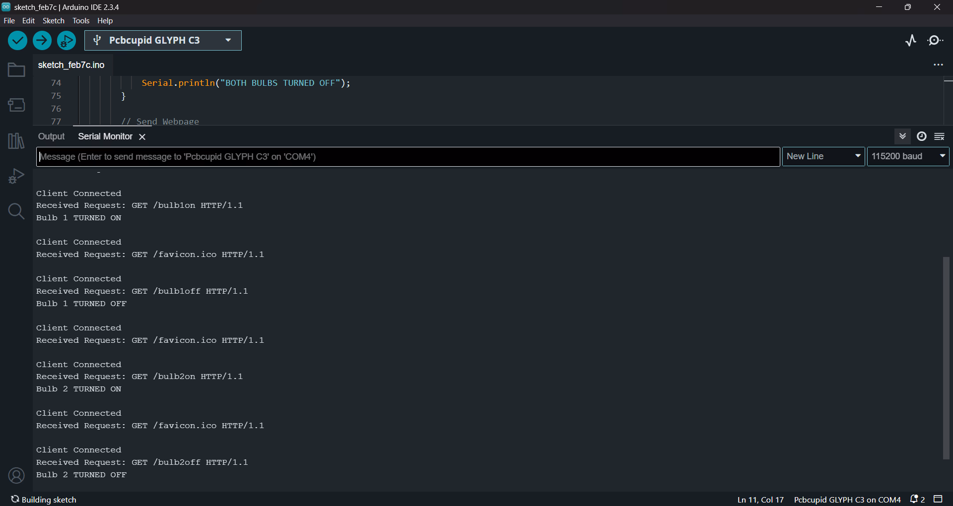
Step 5: Observe the Output on the Serial
After uploading, open the Serial Monitor:
- See WiFi setting up for communication
- Find the IP Address.
- Enter the IP Address in a web browser.
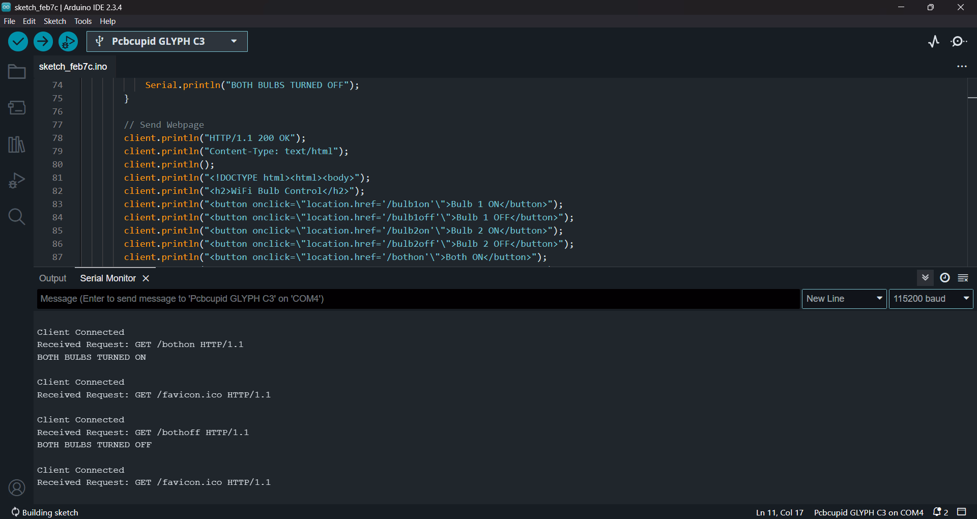
- A Web interface with Graphical Buttons for controlling bulbs will appear
- Click the buttons to turn bulbs ON/OFF.These buttons work by handling HTTP requests to toggle relays, thus controlling the bulbs in the process.
You can see along with the serial monitor, the AC light bulb turn on and turn off accordingly


- Ensure WiFi credentials are correct.
- Some relay modules are active LOW (LOW = ON, HIGH = OFF).
- Ensure the relay power rating matches your bulb requirements.