High-Precision Temperature & Humidity Sensor
Overview
The Gsense-SHT35 is a high-precision temperature and humidity sensor from Sensirion. It is part of the SHT3x series and is known for its high accuracy, reliability, and fast response time. It communicates via I²C and provides digital output for temperature and relative humidity readings.
This sensor can be used with the Glyph development board to measure environmental temperature and humidity. The sensor provides high accuracy and stability, making it suitable for precise atmospheric monitoring.
Pin Configuration
- VCC (RED) - 3.3V
- GND (BLACK) – GND
- SDA (YELLOW)– GPIO (SDA)
- SCL (BLUE) – GPIO (SCL)
Key Features of SHT35
- Operating Voltage: 2.15~5.5V
- Operating Current (AVG) : 1.5mA
- Humidity Accuracy: ±1.5%RH
- Humidity Detection Range: 0%RH~100%RH
- Temperature Accuracy: ±0.2℃
- Temperature Detection Range: -40℃~125℃
- Interface: I²C (address 0x44 or 0x45)
- Response Time: ~2 seconds (humidity)
- Power Consumption: Low power, ideal for battery-powered applications.
Application
- HVAC Systems: HVAC systems to monitor and control temperature and humidity, ensuring comfortable indoor environments.
- Weather Stations: These sensors are used in weather stations to measure temperature and humidity for weather forecasting.
- Industrial Monitoring: The SHT35 is used in various industrial settings to monitor temperature and humidity, which can affect production processes and equipment performance.
- Smart Agriculture:The SHT35 can be used in agriculture to monitor soil and air temperature and humidity, optimizing irrigation and crop management.
This guide will help you interface an SHT35 Temperature and Humidity sensor GLYPH-C6(but any GLYPH development board from the ESP32 Series should work)
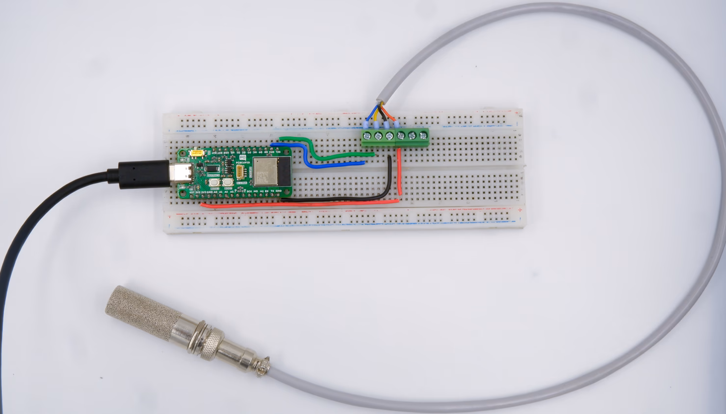
Step 1: Hardware Required
- GLYPH-C6 Board
- GSense SHT35
- Breadboard
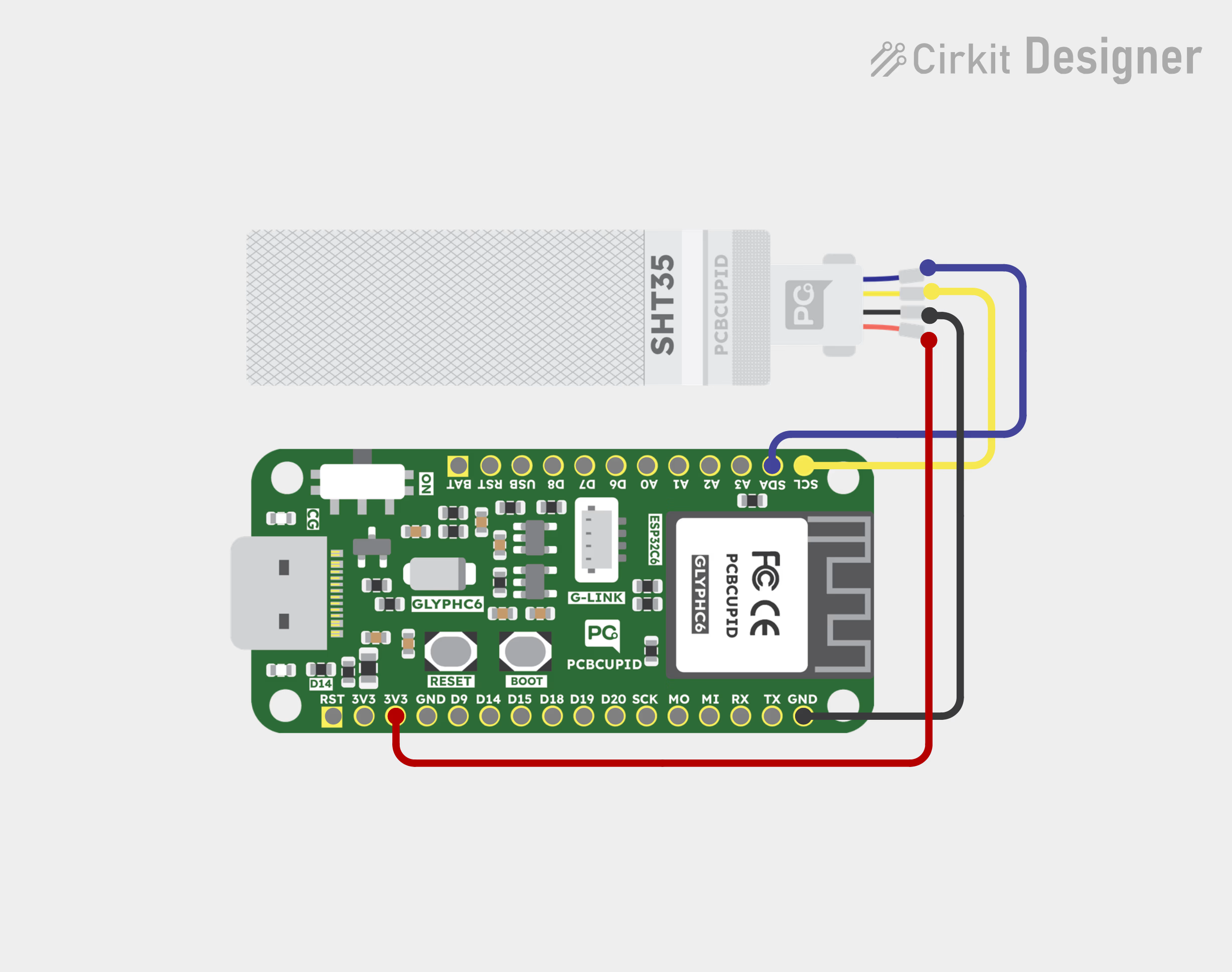
Step 2: Circuit Diagram
You can use either the Gsense SHT35 Industrial or Hobby variant. The pinouts for both are shown in the figure along with the circuit connection
- Connect VCC of the sensor to +3.3V of the GLYPH board
- Connect SDA of the sensor to the SDA(GPIO4) of the GLYPH board
- connect SCL of the sensor to the SCL(GPIO5) of the GLYPH board
- Connect GND of the sensor to GROUND of the GLYPH board
Step 3: Code Setup
- Open Arduino IDE
- Install the Necessary Libraries
Download and install Adafruit_SHT31, this library works for SHT3x Series. - Enter the following code into the Arduino IDE
#include <Wire.h>              // Include the Wire library for I2C communication
#include "Adafruit_SHT31.h"    // Include the Adafruit SHT31 library (compatible with SHT35)

// Define I2C pins for GlyphC6
#define SDA_PIN 4  // GPIO4 as SDA (I2C Data)
#define SCL_PIN 5  // GPIO5 as SCL (I2C Clock)

// Create an instance of the SHT31 class (compatible with SHT35)
Adafruit_SHT31 sht35 = Adafruit_SHT31();

void setup() {
    Serial.begin(115200);  // Start serial communication at 115200 baud rate

    // Wait for the serial monitor to open (useful for debugging)
    while (!Serial) {
        delay(1000);
    }

    Serial.println("SHT35 Sensor Test with GlyphH2");

    // Initialize I2C communication with the defined SDA and SCL pins
    Wire.begin(SDA_PIN, SCL_PIN);

    // Initialize the SHT35 sensor with its default I2C address (0x45 is the alternate address)
    if (!sht35.begin(0x44)) {
        Serial.println("Couldn't find SHT35 sensor! Check wiring.");
        delay(1000); // Wait before retrying
    } else {
        Serial.println("SHT35 sensor found!");
    }
}

void loop() {
    // Read temperature in Celsius
    float temp = sht35.readTemperature();

    // Read humidity in percentage
    float humidity = sht35.readHumidity();

    // Check if the readings are valid (not NaN)
    if (!isnan(temp) && !isnan(humidity)) {
        Serial.print("Temperature: ");
        Serial.print(temp);
        Serial.println(" *C");

        Serial.print("Humidity: ");
        Serial.print(humidity);
        Serial.println(" %RH");
    } else {
        Serial.println("Failed to read from SHT35 sensor!");
    }

    delay(2000);  // Wait 2 seconds before taking the next reading
}
Step 4: Upload the Code
- Connect the Board
- Connect your GLYPH board to your computer
- Select the Board and Port
Do the following settings in your Arduino IDE,
Do the following settings in your Arduino IDE,
Tools > Board > esp32 > Pcbcupid GLYPH C6
For the Pcbcupid GLYPH C6 to appear under Tools > Board > esp32, the esp32 board version installed in the Arduino IDE should be greater than or equal to 3.1.0.
Tools > Portand select the port connected to your GLYPH.Tools > USB CDC on Boot >Enabled
If USB CDC on BOOT not enabled, you won't be seeing any serial data on Arduino IDE.
- Upload the Code
- Click the upload button (➡️ icon) or use the shortcut
CTRL + Uin Arduino IDE to upload the code to the board.
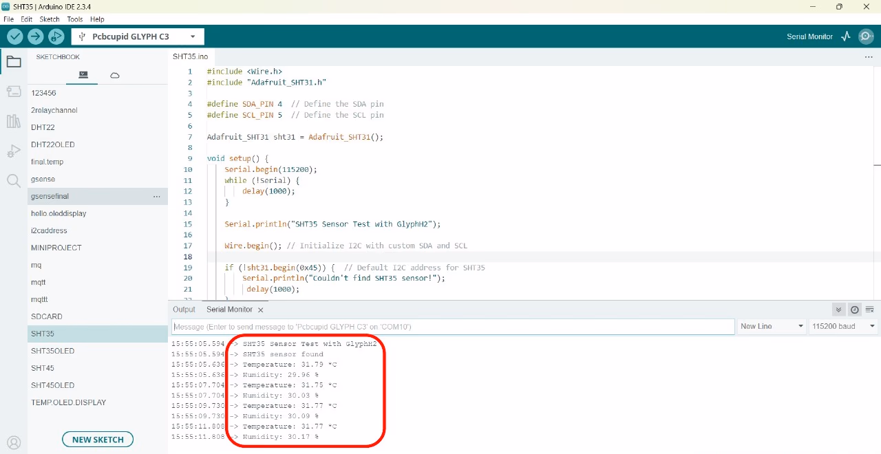
Step 5: Observe the Output on the Serial Monitor
The Serial Monitor should start displaying the Humidity, Temperature and Heat Index values of the surrounding air like this: