Gsense 2-CHANNEL ICS43434 I2S Microphone
Overview
A dual-channel microphone is a device that captures audio signals in two independent channels, typically for stereo or two separate audio sources.
The ICS-43434 digital I2S output bottom port microphone. The complete ICS-43434 solution consists of a MEMS sensor, signal conditioning, an analog-to-digital converter, decimation and antialiasing filters, power management, and an industry standard 24-bit I²S interface. The I²S interface allows the ICS-43434 to connect directly to digital processors, such as DSPs and microcontrollers, without the need for an audio codec in the system.
The ICS-43434 has multiple modes of operation: High Performance, Low Power (AlwaysOn) and Sleep. The ICS-43434 has high SNR and 120 db SPL AOP in all operational modes.
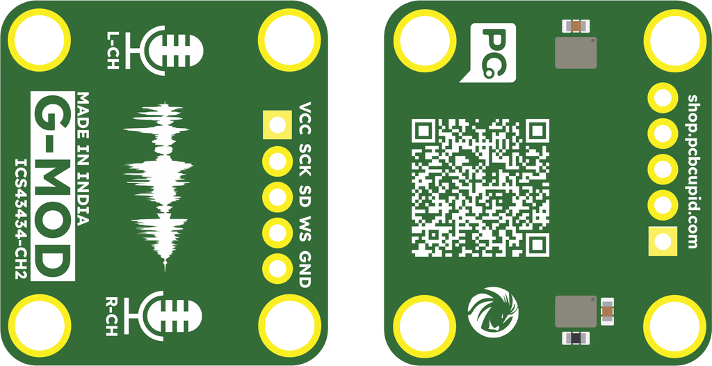
Pin Configuration
- VDD: Power supply for the microphone (1.62V to 3.63V).
- GND: Ground connection.
- WS: Word Select (Frame Sync) input for I²S interface.
- SCK: Serial Clock input for I²S interface.
- SD: Serial Data output.
- L/R: Left/Right channel select. Determines whether the device outputs data on the left or right channel.
Key Features
- Operating Voltage: 1.62V to 3.63V
- Current Consumption (Typical): 490 µA
- Sleep Current : 12uA
- Acoustic Overload Point: 120 dB SPL
- Signal-to-Noise Ratio (SNR): 65 dB(A)
- Frequency Response: 60 Hz to 20 kHz
- Sensitivity: -26 dBFS ±1 dB
- Interface: I²S (Integrated Interchip Sound)
- Output Format: 24-bit, two’s complement
- Channel Selection: Left/Right selectable via L/R pin
- Application Suitability: Optimized for voice capture and far-field audio
Applications
- Stereo Recording: Used in music recording, film production, and live performances for spatial sound capture.
- Dual-Source Recording: Captures two separate audio sources simultaneously (e.g., interviews or instruments).
- Podcasting and Streaming: Provides high-quality, independent channels for voice and background sounds.
- Surround Sound: Integrated into systems for 3D sound environments.
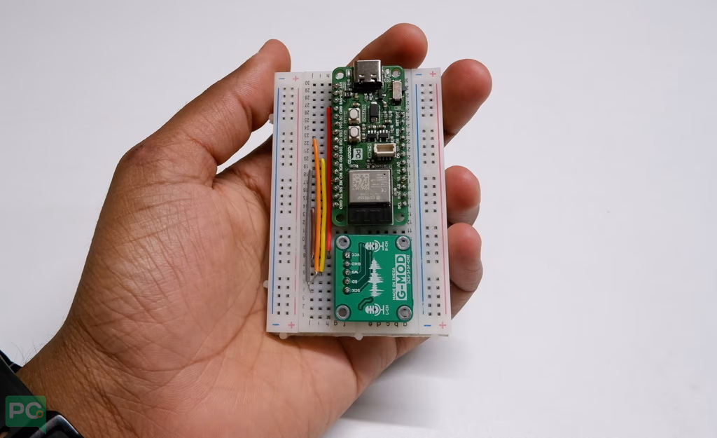
Step 1: Hardware Required
- Glyph Boards
- Gsense 2CH Microphone
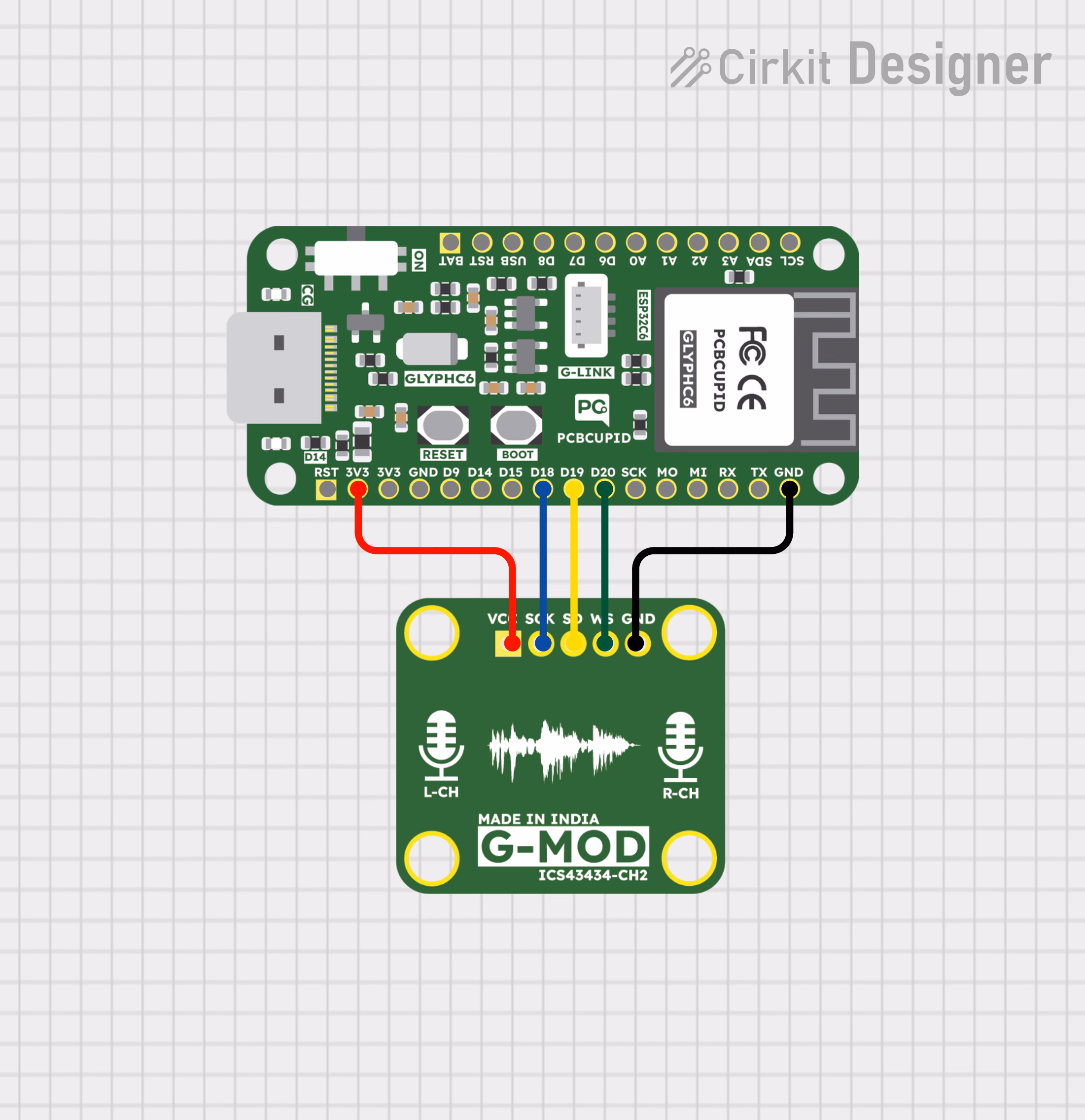
Step 2: Circuit Diagram
Step 3: Code Setup
- Open Arduino IDE.
- Make sure to install the "Audio Tool" library
- Copy and paste the following code into the Arduino IDE:
#include "AudioTools.h"

AudioInfo info(44100, 2, 32);
I2SStream i2sStream; // Access I2S as stream
CsvOutput<int32_t> csvOutput(Serial);
StreamCopy copier(csvOutput, i2sStream); // copy i2sStream to csvOutput

// Arduino Setup
void setup(void)
{
    Serial.begin(115200);
    AudioToolsLogger.begin(Serial, AudioToolsLogLevel::Info);

    auto cfg = i2sStream.defaultConfig(RX_MODE);
    cfg.copyFrom(info);
    cfg.i2s_format = I2S_STD_FORMAT;  // or try with I2S_LSB_FORMAT
    cfg.pin_ws = 20;
    cfg.pin_bck = 18;
    cfg.pin_data_rx = 19;
    cfg.is_master = true;
    cfg.use_apll = false;
    i2sStream.begin(cfg);

    // make sure that we have the correct channels set up
    csvOutput.begin(info);
}

// Arduino loop - copy data
void loop()
{
    copier.copy();
}
Step 4: Upload the Code
- Connect the Board
- Connect your GLYPH board to your computer
- Select the Board and Port
Do the following settings in your Arduino IDE,
Tools > Board > esp32 > Pcbcupid GLYPH C3
For the Pcbcupid Glyph C3 to appear under Tools > Board > esp32, the esp32 board version installed in the Arduino IDE should be greater or equal to 3.1.0.
Tools > Portand select the port connected to your GLYPH.Tools > USB CDC on Boot >Enabled
If USB CDC on BOOT not enabled, you won't be seeing any serial data on Arduino IDE.
-
Upload the Code
- Click the upload button (➡️ icon) or use the shortcut
CRTL + Uin Arduino IDE to upload the code to the board.
- Click the upload button (➡️ icon) or use the shortcut
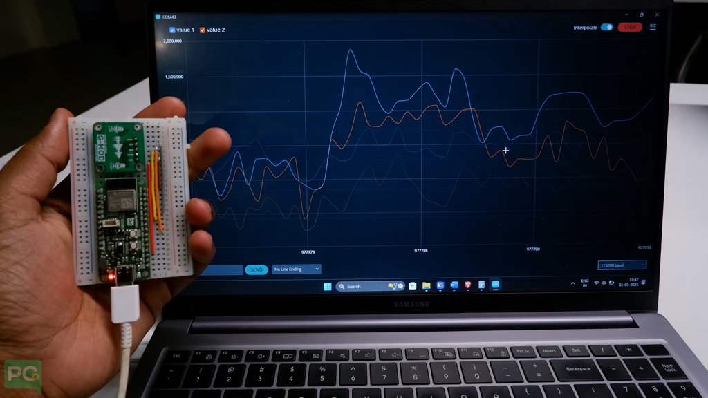
Step 5: Observe the Output
The output can be visualized in the plotter of Arduino IDE, Please check the below image for reference
Output on Arduino IDE 1.x
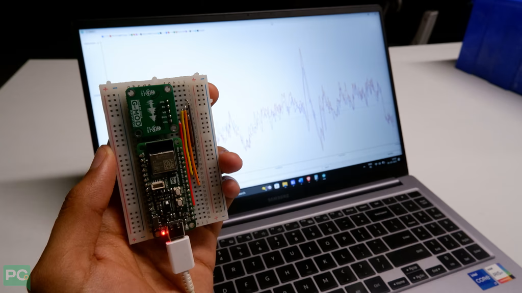
Output on Arduino IDE 2.x