QMC6309 3-Axis Electronic Compass with I²C interface, high stability, and built-in self-test. Perfect for drones, robotics, and navigation.
The QMC6309, produced by QST Corporation, is a compact and energy-efficient digital magnetometer designed to detect magnetic fields across three axes (X, Y, Z). It integrates both magnetic sensing elements and signal-conditioning circuitry into a single silicon chip.The QMC6309 stands out as a diminutive, energy-efficient, and accurate 3-axis magnetometer solution, ideal for compact and embedded electronics like VR trackers and flight controllers. With its seamless integration of sensing and signal conditioning, it provides high-precision magnetic field data with minimal PCB footprint.
//You can download the PCBCUPID_QMC6309 library from here : https://github.com/pcbcupid/PCBCUPID-QMC6309#include <Wire.h>#include "PCBCUPID_QMC6309.h"#include "ExponentialFilter.h"PCBCUPID_QMC6309 mag(Wire);// Calibrated offsetsconst float x_offset = 3485.0;const float y_offset = 1290.0;const float declination = 0.22;// Filter object: 0.2 weight (20%)ExponentialFilter headingFilter(0.2, 0.0);void setup() { Serial.begin(115200); delay(1000); if (!mag.begin()) { Serial.println("Magnetometer init failed"); while (1); } Serial.println("Heading with Exponential Filter");}void loop() { int16_t x, y, z; if (mag.readRaw(x, y, z)) { float x_cal = x - x_offset; float y_cal = y - y_offset; float heading = atan2(-x_cal, y_cal) + declination; if (heading < 0) heading += 2 * PI; if (heading > 2 * PI) heading -= 2 * PI; float headingDeg = heading * 180.0 / PI; // Apply exponential filter headingFilter.update(headingDeg); float smoothedHeading = headingFilter.get(); Serial.print("Heading: "); Serial.print(smoothedHeading, 1); Serial.print("° ("); Serial.print(mag.headingToDirection(smoothedHeading)); Serial.println(")"); } delay(200);}
Connect the Board
Connect your GLYPH board to your computer
Select the Board and Port
Do the following settings in your Arduino IDE,
Tools > Board > esp32 > Pcbcupid GLYPH C3
For the Pcbcupid Glyph C3 to appear under Tools > Board > esp32, the esp32 board version installed in the Arduino IDE should be greater or equal to 3.1.0.
Tools > Port and select the port connected to your GLYPH.
Tools > USB CDC on Boot >Enabled
If USB CDC on BOOT not enabled, you won’t be seeing any serial data on Arduino IDE.
Upload the Code
Click the upload button (➡️ icon) or use the shortcut CRTL + U in Arduino IDE to upload the code to the board.
The output shows the smoothed compass heading in degrees (0–360°) along with its cardinal direction (e.g., N, NE, E, SE, etc.).
Might not have accurate reading as this was not the intended purpose, This module is very useful to find strong magnetic field in 3 dimensional space.
For the Pcbcupid Glyph C3 to appear under Tools > Board > esp32, the esp32 board version installed in the Arduino IDE should be greater or equal to 3.1.0.
Tools > Port and select the port connected to your GLYPH.
Tools > USB CDC on Boot >Enabled
If USB CDC on BOOT not enabled, you won’t be seeing any serial data on Arduino IDE.
Upload the Code
Click the upload button (➡️ icon) or use the shortcut CRTL + U in Arduino IDE to upload the code to the board.
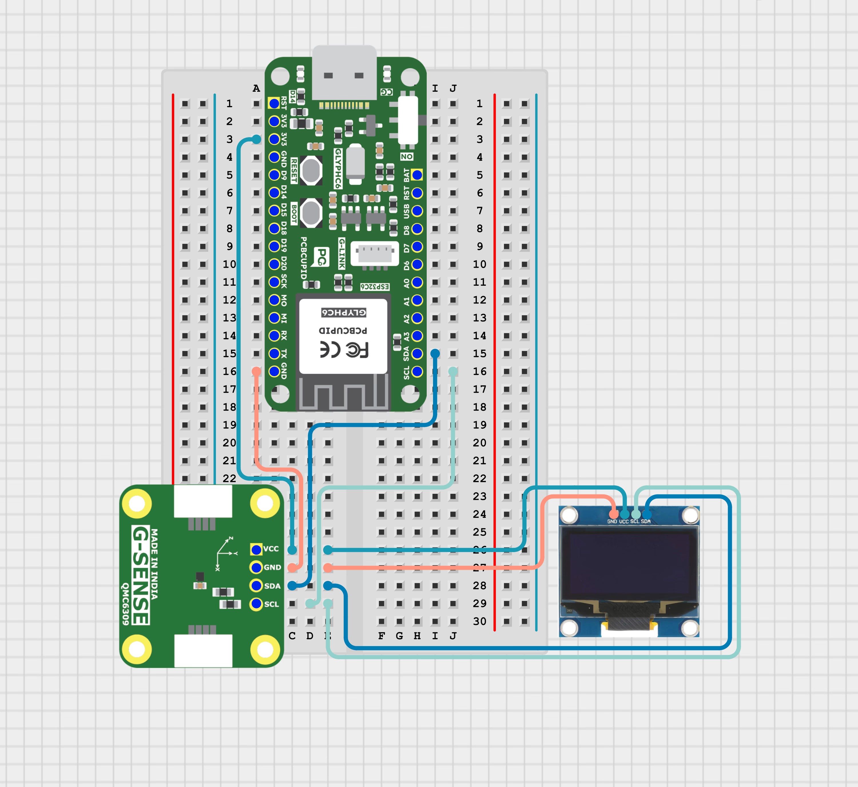
outputs real-time X, Y, Z magnetometer readings as both serial text and dynamic bar graphs on an OLED, showing deviation from running average with percentage values.