The Capacitive Slider is a touch-sensitive input module based on the CAP1203 IC. It provides high-precision touch detection for sliders and buttons, making it perfect for custom user interfaces, control panels, and interactive projects.
This guide provides a step-by-step explanation to help you integrate the Gsense-Touch Sensor for touch detection using the G-Sense module on the GLYPH-H2 board. The system detects left, middle, and right gestures and provides real-time feedback via the Serial Monitor.
Features
- 3-Channel Capacitive Touch – detects left, middle, and right touch/slide gestures
- Swipe Detection – recognizes directional swipes across the slider
- Digital Output – provides clear HIGH/LOW signals for each touch channel over I2C
- Low Power Consumption – suitable for battery-operated applications
- Integrated Signal Processing – built-in debounce and touch sensing algorithms
- Compact Module – easy integration with boards like GLYPH
Applications
- Gesture-Control Interfaces – control devices or menus with simple swipes
- Consumer Electronics – touch sliders for volume, brightness, or selection
- Robotics & Automation – simple human-machine interface (HMI) for commands
- IoT Devices – intuitive touch-based input for compact devices
- Gaming & VR Controllers – gesture input for interactive experiences
- Wearable Devices – lightweight, low-power input sensor for compact systems
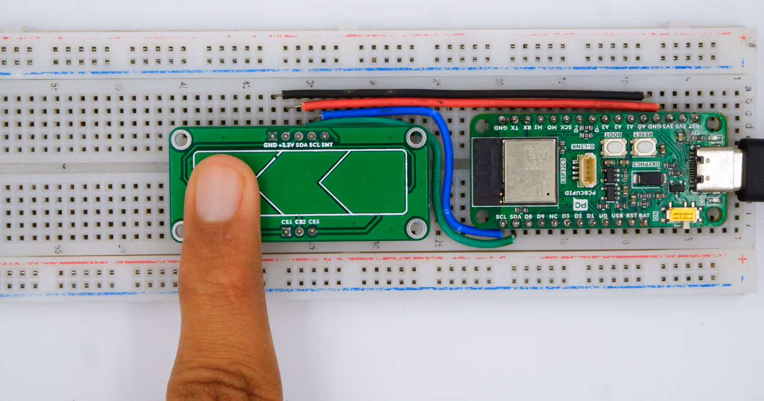
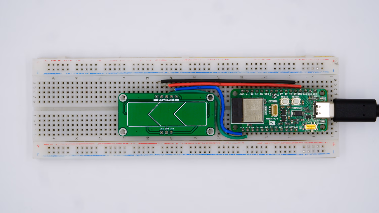
Step 1: Hardware Required
- Glyph Board
- Gsense Capacitive Touch Slider
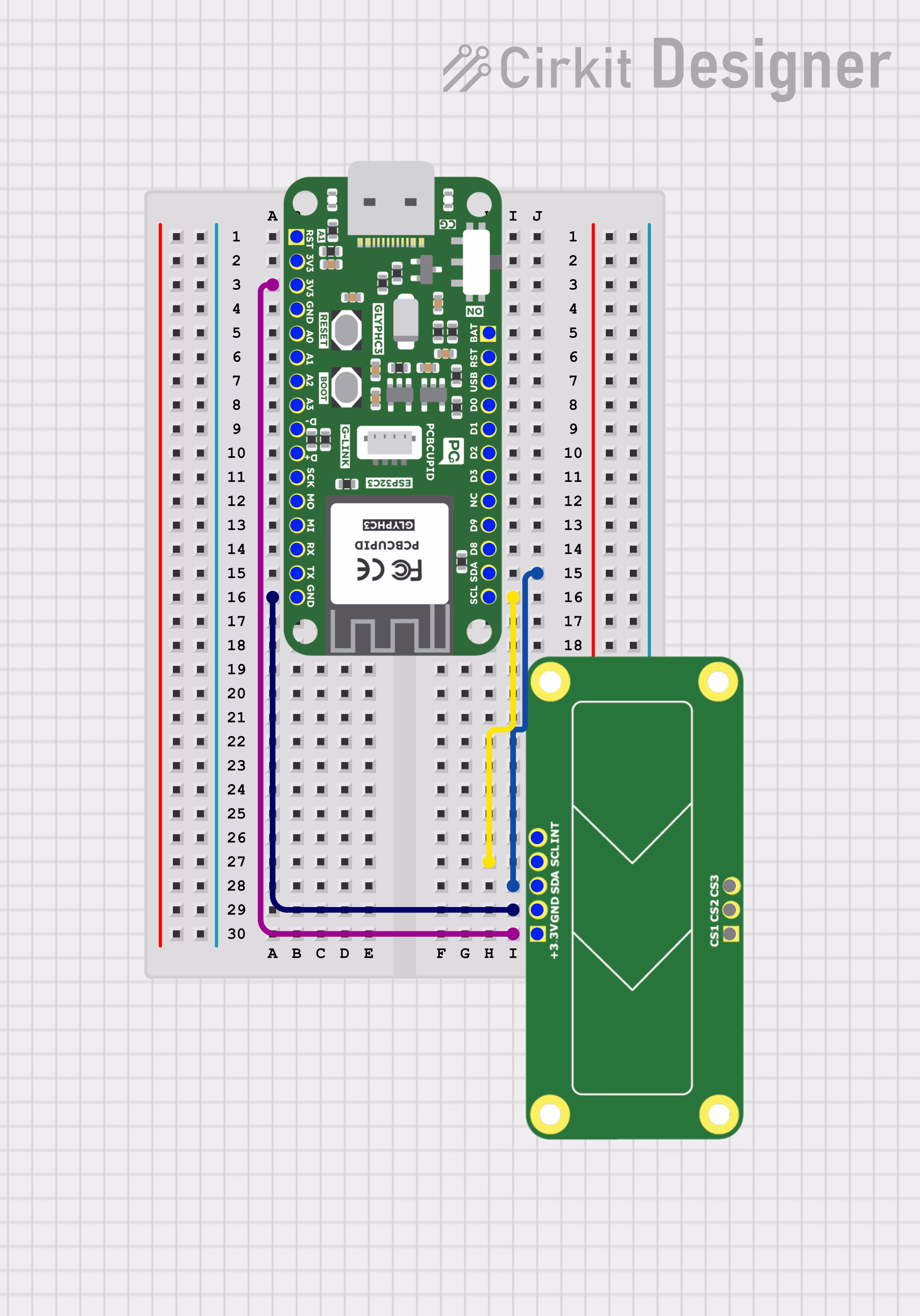
Step 2: Circuit Diagram
Step 3: Code Setup
Step 4: Upload the Code
- Connect the Board
- Connect your GLYPH board to your computer
-
Select the Board and Port
Do the following settings in your Arduino IDE,
Tools > Board > esp32 > Pcbcupid GLYPH C3
Tools > Portand select the port connected to your GLYPH.Tools > USB CDC on Boot >Enabled
- Upload the Code
- Click the upload button (➡️ icon) or use the shortcut
CTRL + Uin Arduino IDE to upload the code to the board.
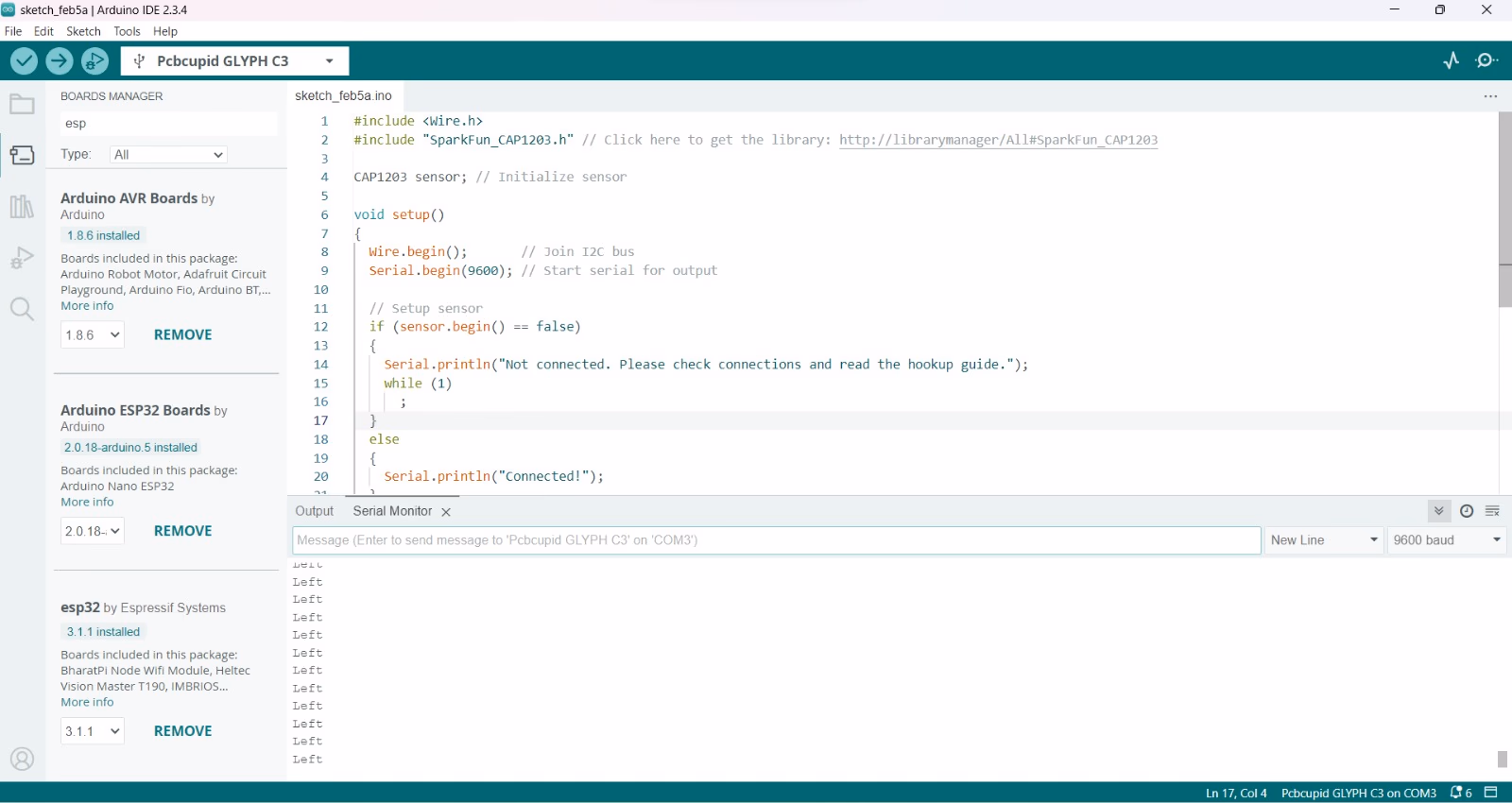
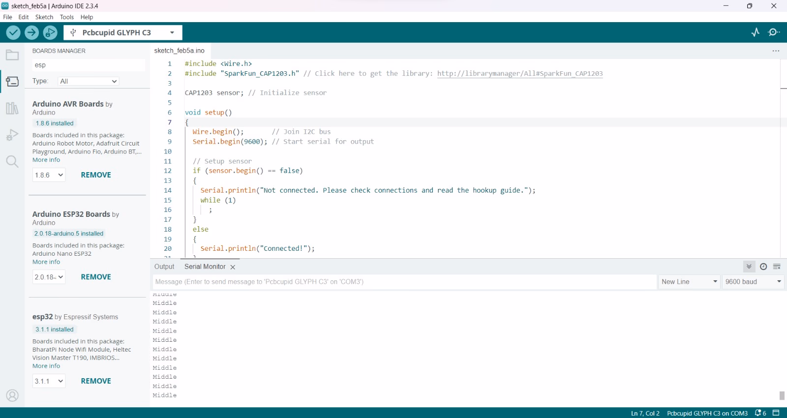
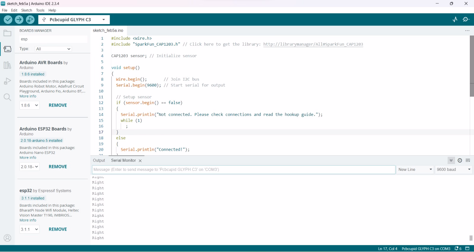
Step 5: Observe the Output
When you touch different sides of the Sensor, you can see the Serial Monitor Output as follows: