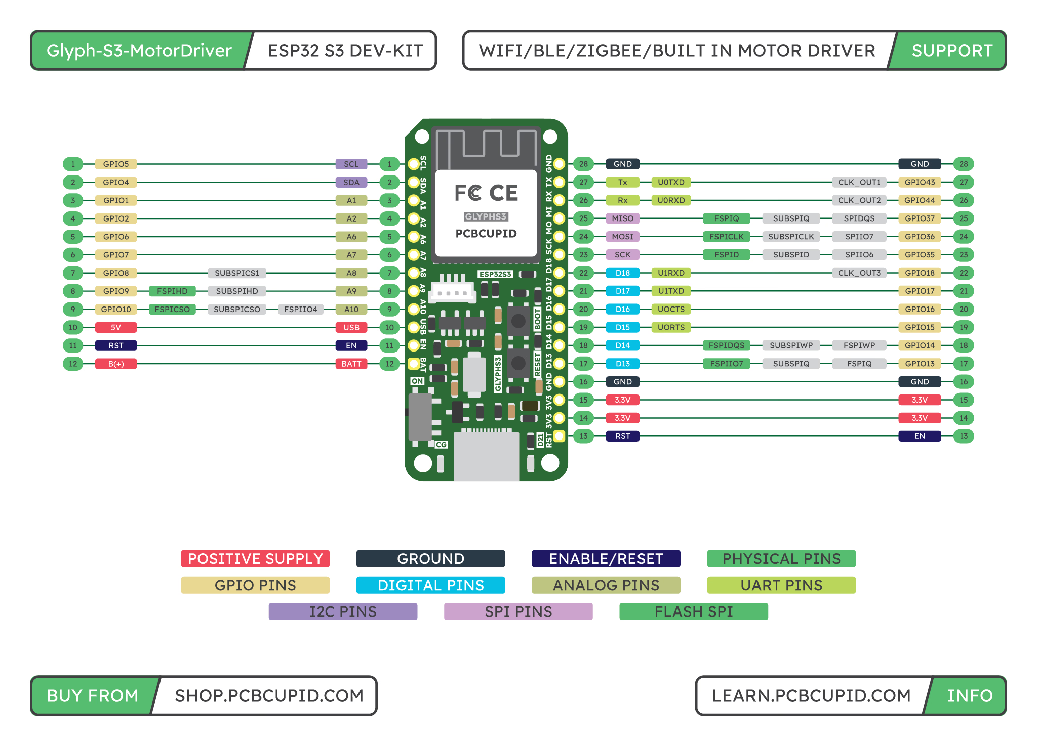
The pinout diagram shows the board labels and connector locations. The tables below list the nets and GPIO assignments from the board schematic.
J1: 12-pin header
J2: 16-pin header
Additional solder pads
These schematic pads expose extra power and GPIO connections:Glink connector J5
J5 is the Qwiic/STEMMA QT-compatible Glink connector.
Motor connectors
J7 and J8 are 2-pin Molex PicoBlade motor output connectors wired to the onboard TB6612FNG:
Connect one brushed DC motor across each pair. A bipolar stepper motor uses both output pairs for its two windings.
Motor-driver control GPIOs
These ESP32-S3 GPIOs are connected internally to the TB6612FNG control inputs:
These pins are used by the onboard motor driver. Use the motor power notes before wiring motors.
Battery and USB-C
- Battery connector J6: Pin 1 GND; pin 2 Bat_PWR (battery positive).
- USB-C connector J4: USB power and native USB data/programming.