PCF8563-RTC
Overview
The PCF8563 is a low-power CMOS real-time clock/calendar (RTC) IC with an I²C-bus interface from NXP. It keeps track of time and date, including seconds, minutes, hours, days, months, years, and has programmable alarms and timers.
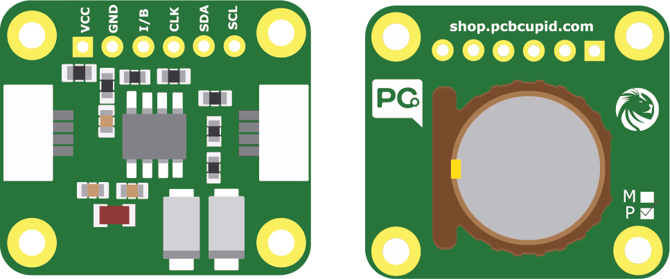
Check the back of the RTC module: modules marked “M” use the MCP79412, while those marked “P” use the PCF8563.
It is widely used in embedded systems, IoT devices, and portable electronics because of its ultra-low power consumption and accuracy.
The PCF8563 RTC is a low-power, I²C-based real-time clock with alarms and timers, ideal for keeping accurate time in embedded systems and low-power applications.
Pin Configuration
- VCC → VCC
- GND → GND
- CLK → SCK / Any GPIO
- SDA → SDA
- SCL → SCL
- I → Any GPIO / Can be used as interrupt
Key Features
- I²C (2-wire) communication interface (up to 400 kHz Fast Mode).
- Additional RTC function:
- Seconds, minutes, hours, days, weekdays, months, years.
- Automatic leap year correction (up to year 2099).
- Programmable clock output (32.768 kHz, 1 Hz, etc.).
- Two independent alarms (daily/weekly programmable).
- Countdown timer with interrupt capability.
- Ultra-low operating current (typically < 1 µA in time-keeping mode).
- Operating voltage: 1.0V – 5.5V (suitable for battery operation)
Applications
- IoT devices (timestamping sensor data).
- Clocks, watches, and portable devices.
- Data loggers.
- Industrial control and automation.
- Energy meters.
- Battery-powered embedded systems.
Step 1: Hardware Required
- Glyph Boards
- GMOD PCF8563-RTC
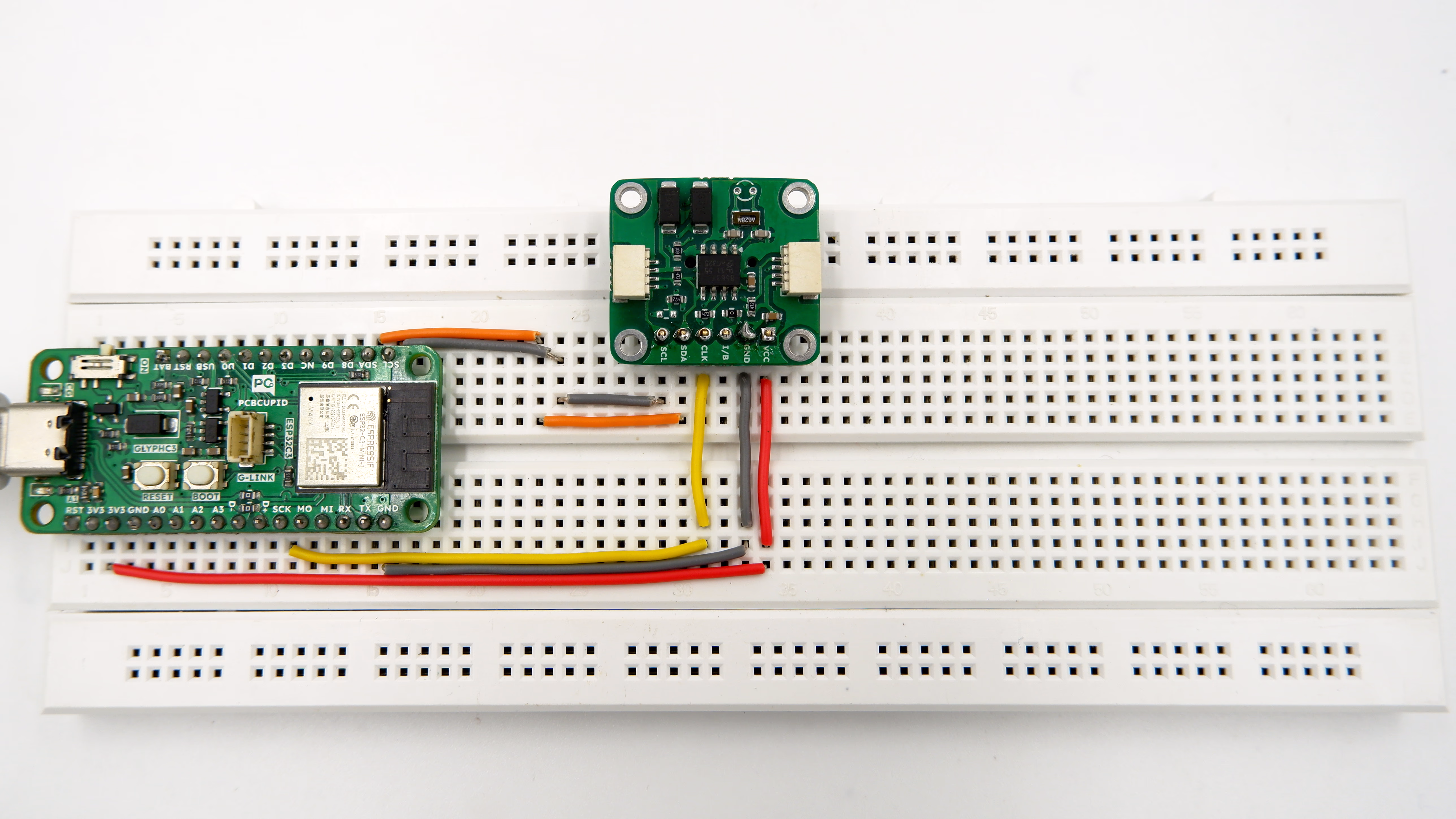
Step 2: Circuit Diagram

Step 3: Code Setup
- Open Arduino IDE.
- Make sure to install the library
- Copy and paste the following code into the Arduino IDE:
#include <PCF8563.h>

PCF8563 pcf;

void setup() {
  Serial.begin(9600);
  pcf.init();//initialize the clock

  pcf.stopClock();//stop the clock

  //set time to to 31/3/2018 17:33:0

  pcf.setYear(18);//set year
  pcf.setMonth(3);//set month
  pcf.setDay(31);//set dat
  pcf.setHour(17);//set hour
  pcf.setMinut(33);//set minut
  pcf.setSecond(0);//set second

  pcf.startClock();//start the clock
}

void loop() {
  Time nowTime = pcf.getTime();//get current time

  //print current time
  Serial.print(nowTime.day);
  Serial.print("/");
  Serial.print(nowTime.month);
  Serial.print("/");
  Serial.print(nowTime.year);
  Serial.print(" ");
  Serial.print(nowTime.hour);
  Serial.print(":");
  Serial.print(nowTime.minute);
  Serial.print(":");
  Serial.println(nowTime.second);
  delay(1000);
}
Step 4: Upload the Code
- Connect the Board
- Connect your GLYPH board to your computer
- Select the Board and Port
Do the following settings in your Arduino IDE,
Tools > Board > esp32 > Pcbcupid GLYPH C3
For the Pcbcupid Glyph C3 to appear under Tools > Board > esp32, the esp32 board version installed in the Arduino IDE should be greater or equal to 3.1.0.
Tools > Portand select the port connected to your GLYPH.Tools > USB CDC on Boot >Enabled
If USB CDC on BOOT not enabled, you won't be seeing any serial data on Arduino IDE.
-
Upload the Code
- Click the upload button (➡️ icon) or use the shortcut
CRTL + Uin Arduino IDE to upload the code to the board.
- Click the upload button (➡️ icon) or use the shortcut
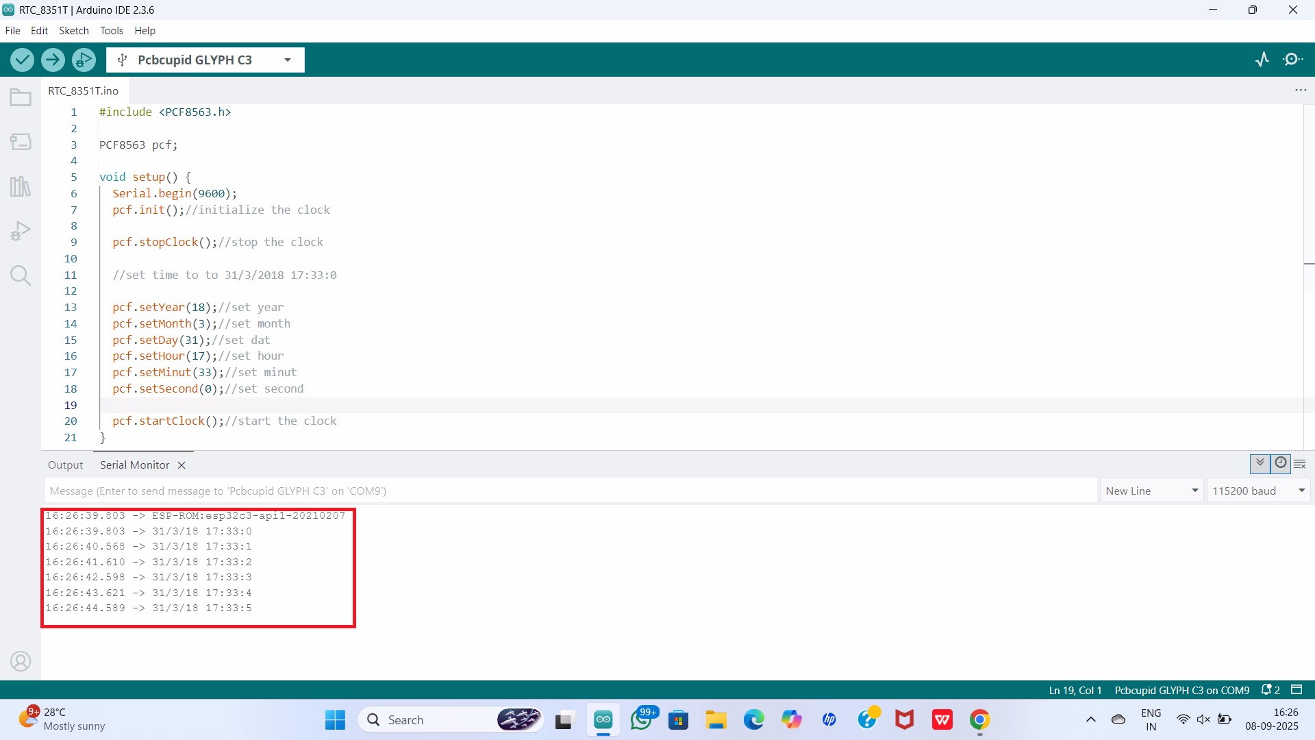
Step 5: Observe the Output
The RTC module tracks time independently. With the onboard 3V Lithium Cell (CR1220), it continues timekeeping even when the GLYPH is powered off.