A Micro SD Card Module is a compact circuit designed to interface a microcontroller (e.g., Arduino, ESP32, Raspberry Pi) with a Micro SD card for data storage, retrieval, and management. This module can work both on SPI and SDIO mode, in this particular doc you will understand how to interface SD card with GLYPH in SPI mode.
Pin Configuration
- 3V3: Power supply for the module (3.3V).
- D1 : data pin, used for data transfer
- SCK: Clock single for SPI communication
- MO : Master out slave in
- MI : Master in Slave out
- CS : chip select
- GND : ground
- D2 : data pin, used for data transfer
Key Features
- Supports microSD Cards
- SPI & SDIO Interface Compatible
- Plug-and-Play Interface
- Compact and Lightweight Design
- File System Compatibility
- Low Power Consumption
- Push-push type socket
Application
- Data Logging: Storing sensor data, logs, or measurements in projects like weather monitoring or IoT.
- Media Storage: Saving and retrieving images, videos, or audio files.
- Boot Media: Used in systems like Raspberry Pi for storing operating systems.
- Portable Data Transfer: Enabling easy data transport between devices.
Step 1: Hardware Required
- Glyph Boards
- G-MOD Micro SDCard Module
Step 2: Circuit Diagram

Step 3: Code Setup
- Open Arduino IDE.
- Copy and paste the following code into the Arduino IDE:
#include <SPI.h>
#include <SD.h>
#define SD_CS 17 // Change this to match your Glyph board's SD card CS pin
//GMOD-- GLYPH
//3v3-- 3v3
//sck-- sck
//MO -- MO
//MI-- MI
//GND-- GND
void listFiles(File dir, int numTabs = 0) {
while (true) {
File entry = dir.openNextFile();
if (!entry) {
break; // No more files
}
for (int i = 0; i < numTabs; i++) {
Serial.print("\t");
}
Serial.print(entry.name());
if (entry.isDirectory()) {
Serial.println("/");
listFiles(entry, numTabs + 1); // Recursively list directories
} else {
Serial.print("\t");
Serial.println(entry.size(), DEC);
}
entry.close();
}
}
void setup() {
Serial.begin(115200);
while (!Serial);
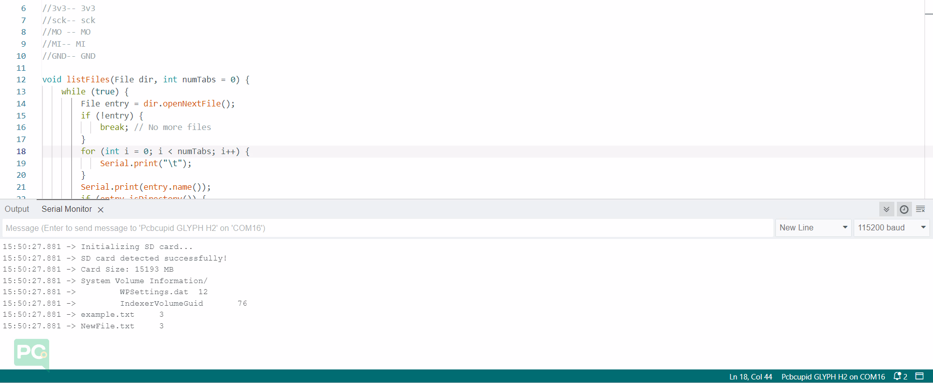
Serial.println("Initializing SD card...");
if (!SD.begin(SD_CS)) {
Serial.println("SD card not detected!");
return;
}
Serial.println("SD card detected successfully!");
// Print card information
uint32_t cardSize = SD.cardSize() / (1024 * 1024);
Serial.print("Card Size: ");
Serial.print(cardSize);
Serial.println(" MB");
// List files on SD card
File root = SD.open("/");
listFiles(root);
root.close();
}
void loop() {
// Nothing to do in the loop
}
Step 4: Upload the Code
- Connect the Board
- Connect your GLYPH board to your computer
- Select the Board and Port
Do the following settings in your Arduino IDE,
Tools > Board > esp32 > Pcbcupid GLYPH C3
For the Pcbcupid Glyph C3 to appear under Tools > Board > esp32, the esp32 board version installed in the Arduino IDE should be greater or equal to 3.1.0.
Tools > Port and select the port connected to your GLYPH.Tools > USB CDC on Boot > Enabled
If USB CDC on BOOT not enabled, you won’t be seeing any serial data on Arduino IDE.
-
Upload the Code
- Click the upload button (➡️ icon) or use the shortcut
CRTL + U in Arduino IDE to upload the code to the board.
Step 5: Observe Output on Serial Monitor