A lithium charger is a versatile power management module used to safely charge either a single (1S) or double (2S) lithium-ion battery pack. It employs the Constant Current / Constant Voltage (CC/CV) method to ensure maximum battery life and safety. This module is ideal for robotics, portable electronics, and any application requiring reliable battery recharging.
⚙️ Charging Mode Configuration
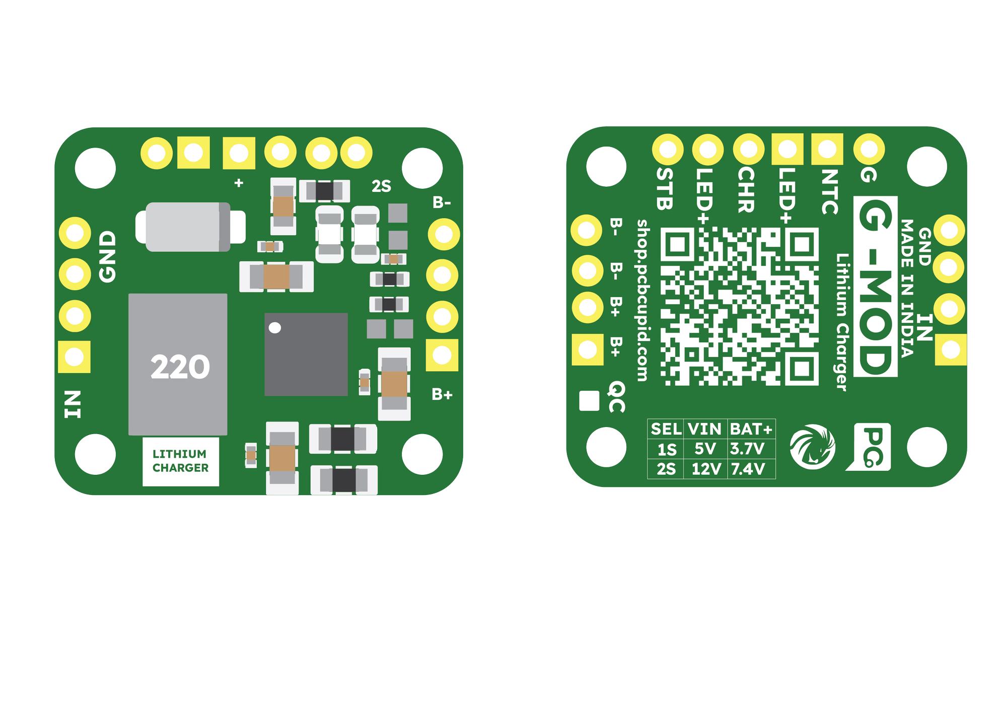
The module can be configured for two different battery types by modifying a hardware solder point on the board labeled 2S.
1. Mode Selection
- 1S Mode (3.7V / 4.2V Full): Leave the 2S solder point OPEN (default).
- 2S Mode (7.4V / 8.4V Full): SHORT (solder) the 2S point to select 2S charging.
2. Input Voltage Requirements
To ensure proper charging, your input power supply must meet the following minimums:
- 1S Mode: 5.0V – 18V DC input.
- 2S Mode: 10V – 18V DC input (12V recommended).
🔌 Pin Configuration
- IN+ – DC Power Input Positive
- GND – DC Power Input Ground
- B+ – Battery Positive Terminal
- B− – Battery Negative Terminal
- G – Ground
- NTC – Temperature sensor input
- LED+ – LED Positive (for external status)
- CHR – Charging status output (Red LED)
- STB – Standby / Full status output (Blue/Green LED)
🚀 Key Features
- Dual Mode Support: Charges 1S (3.7V) and 2S (7.4V) packs.
- High Current Rating: Supports up to 2A default charging current.
- Adjustable Current: The charging current can be varied by changing the current limiting resistors on the board.
- CC/CV Charging: Automatic transition from constant current to constant voltage.
- Status Monitoring: Dedicated pins for external status LEDs.
- Safety: Includes overcharge protection and NTC temperature sensing support.
🛠️ Step 1: Hardware Required
- G-MOD Lithium Charger Module (GM014)
- Lithium-ion Battery:
- 1S: 3.7V Cell
- 2S: 7.4V Battery Pack
- DC Power Supply (5V for 1S, 12V for 2S)
- Connecting Wires
- Screwdriver (for terminal connections)
⚡ Step 2: Circuit Connection
[!IMPORTANT] Always verify the 2S solder point configuration before connecting your battery. Connecting a 1S battery while the board is in 2S mode will damage the battery.

📊 Step 3: Observe the Output
Once connected, the CHR pin will pull low to indicate charging is active. Once the battery reaches its target voltage (4.2V for 1S or 8.4V for 2S), the STB pin will trigger to signal a full charge.
- Current Limiting: If you need to charge smaller batteries, replace the surface-mount current-sensing resistors to lower the 2A output to a safer level for your specific cells.