A Serial Flash Module is a compact memory device designed to interface a microcontroller (e.g., Arduino, ESP32, GLYPH, STM32) for non-volatile data storage, firmware storage, logging, and configuration management. Unlike SD cards, Serial Flash is directly soldered onto the board and communicates typically over SPI (and sometimes QSPI) for high-speed data transfer.
Pin Configuration
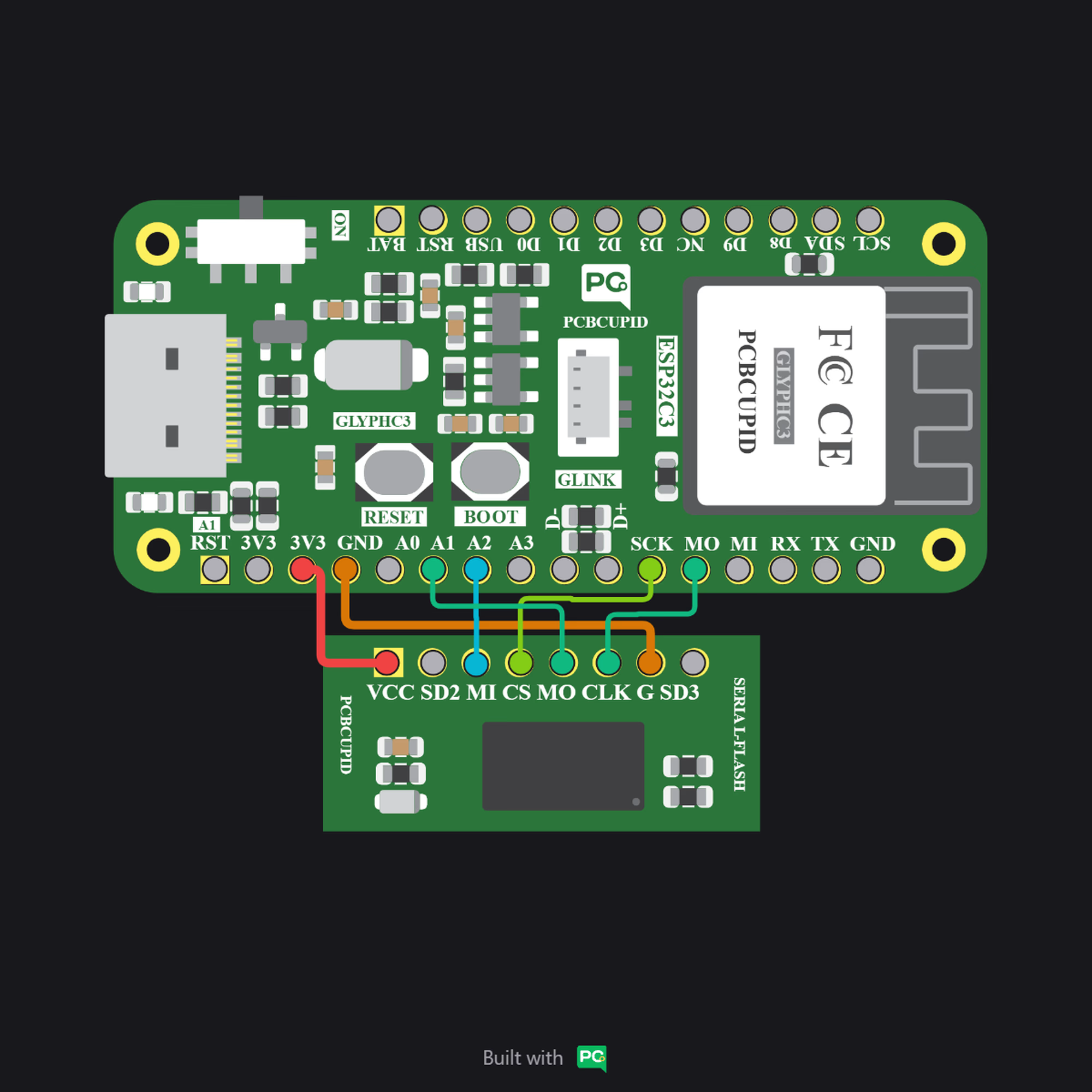
- VCC: Power supply input for the Serial Flash chip (typically 3.3V).
- G (GND): Ground .
- CLK: Serial Clock input for SPI communication
- CS: Chip Select (active LOW). Enables communication with the Serial Flash device.
- MO (MOSI / SI): Master Out Slave In — carries data from the
- MI (MISO / SO): Master In Slave Out — carries data from the Serial Flash to the microcontroller.
- SD2 (IO2): Data line 2. Used in Quad-SPI (QSPI) mode for higher-speed data transfer. In standard SPI mode, this pin is typically unused or acts as a hold function depending on the chip.
- SDI3 (IO3): Data line 3. Used in Quad-SPI (QSPI) mode. In standard SPI mode, this pin may function as Write Protect (WP) or Hold depending on the flash device.
Key Features
- Non-volatile memory (retains data without power)
- SPI / QSPI communication support
- High-speed data transfer
- Compact and small footprint
- Low power consumption
- High endurance (multiple erase/write cycles)
- Sector and block erase capability
- Supports execute-in-place (XIP) in QSPI
- Wide voltage operating range (typically 3.3V)
- Reliable long-term data storage
Application
- Firmware Storage: Storing bootloader, application code, or external program memory in embedded systems.
- OTA Updates: Holding firmware files for over-the-air updates in IoT devices.
- Data Logging: Recording sensor readings, event logs, or system data in real-time applications.
- Configuration Storage: Saving device settings, calibration values, or user preferences.
- Buffer Memory: Temporary storage for data processing in communication or control systems.
- Embedded Systems: Expanding memory capacity in microcontroller-based designs.
Step 1: Hardware Required
- Glyph Boards
- G-MOD Serial flash Module
Step 2: Circuit Diagram
Step 3: Code Setup
- Open Arduino IDE.
- Copy and paste the following code into the Arduino IDE:
Here’s your code with detailed comments added so it’s easier to follow and understand:
Step 4: Upload the Code
- Connect the Board
- Connect your GLYPH board to your computer
- Select the Board and Port
Do the following settings in your Arduino IDE,
Tools > Board > esp32 > Pcbcupid GLYPH C3
For the Pcbcupid Glyph C3 to appear under Tools > Board > esp32, the esp32 board version installed in the Arduino IDE should be greater or equal to 3.1.0.
Tools > Port and select the port connected to your GLYPH.Tools > USB CDC on Boot > Enabled
If USB CDC on BOOT not enabled, you won’t be seeing any serial data on Arduino IDE.
-
Upload the Code
- Click the upload button (➡️ icon) or use the shortcut
CRTL + U in Arduino IDE to upload the code to the board.
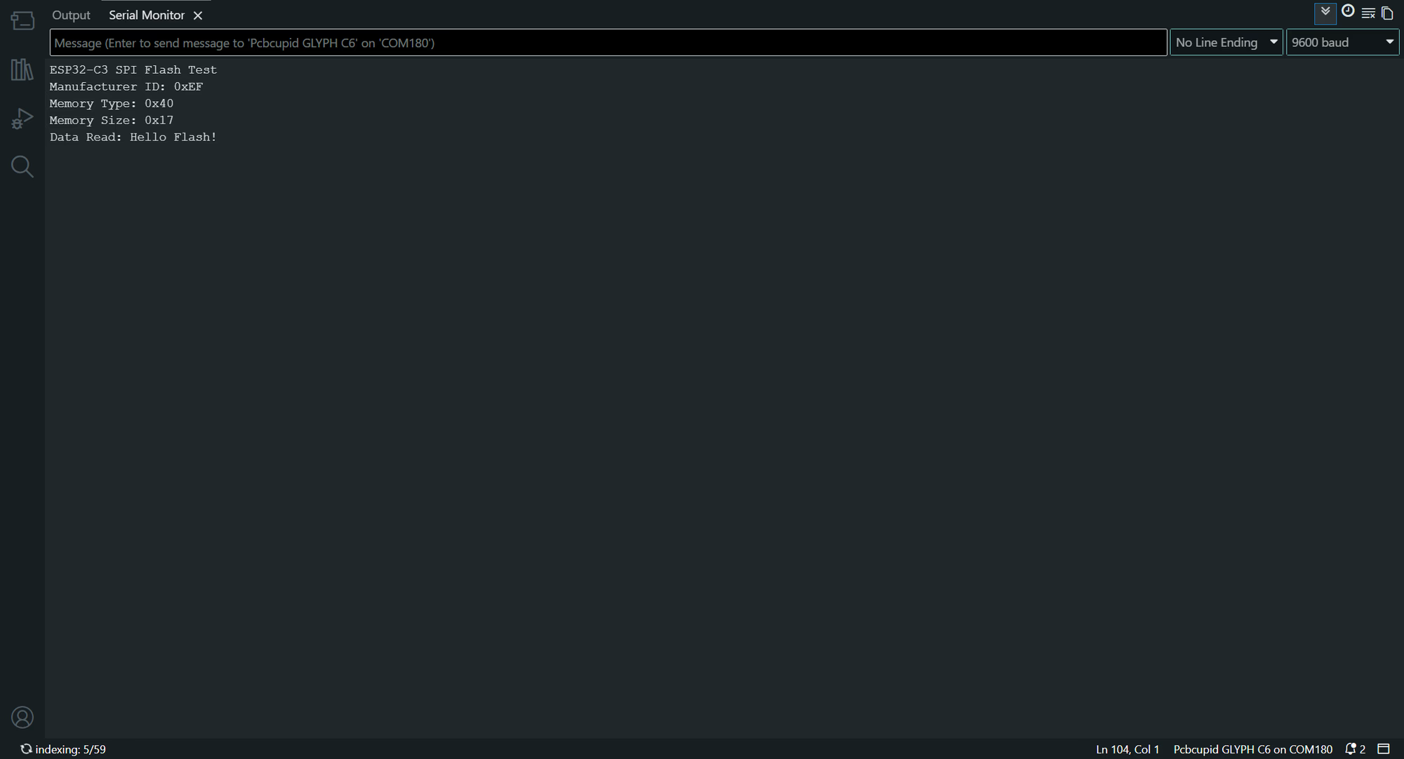
Step 5: Observe Output on Serial Monitor