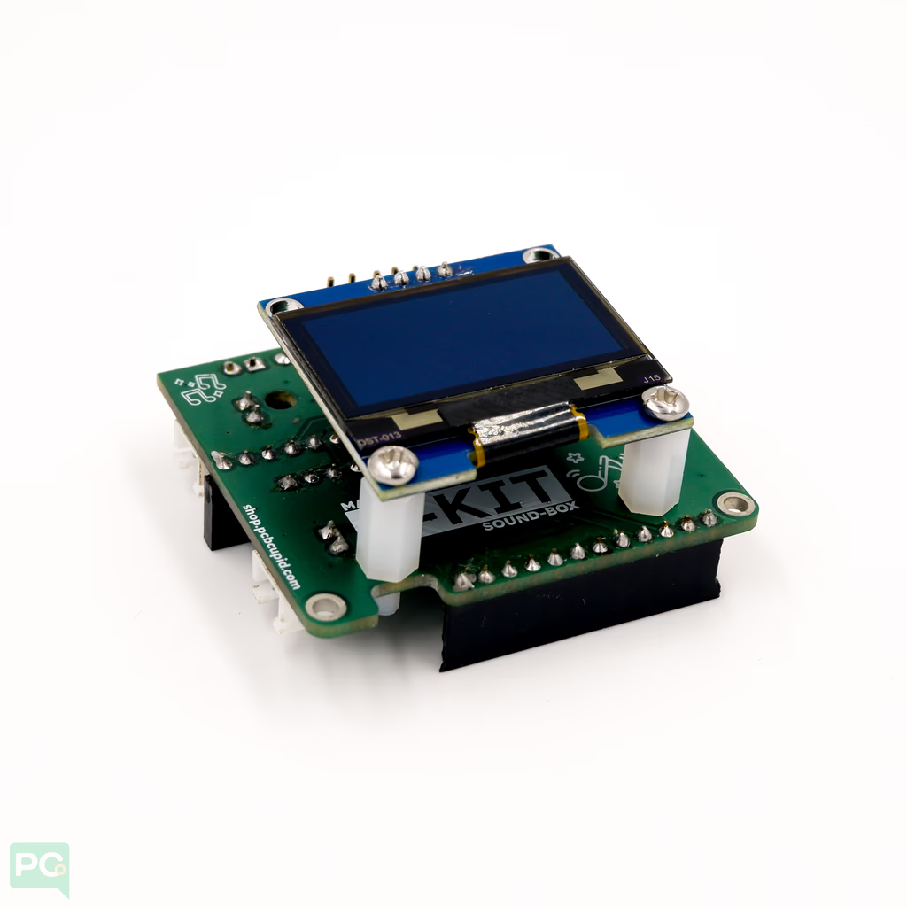
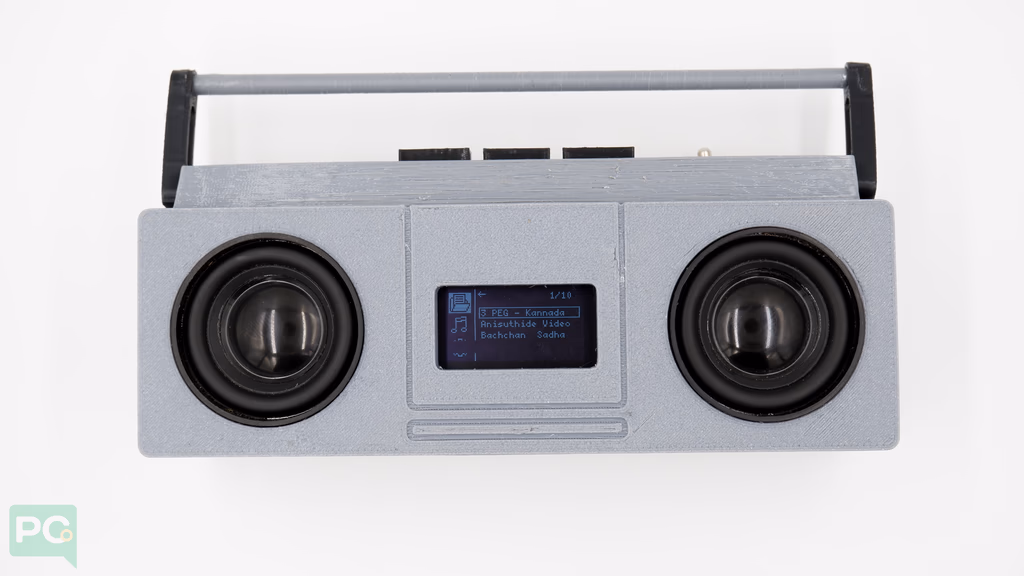
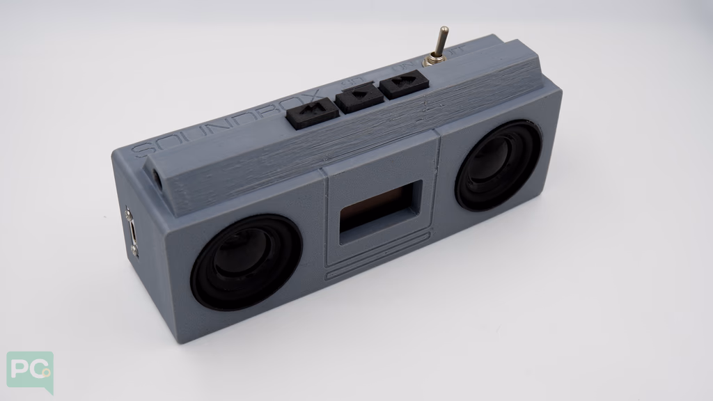
The G-Kit SoundBox is a standalone MP3 player kit built around the Glyph Development Board designed to capture the charm of a vintage boombox while showcasing the power and flexibility of modern modular electronics.
 This project combines digital audio, intuitive UI design, and hands-on hardware interaction in one compact build. It’s not a music player — it’s an educational platform that teaches fundamentals of audio electronics, embedded programming, and system design.
Learn Embedded Audio Design
This project combines digital audio, intuitive UI design, and hands-on hardware interaction in one compact build. It’s not a music player — it’s an educational platform that teaches fundamentals of audio electronics, embedded programming, and system design.
Learn Embedded Audio Design
- Audio Pipeline: From MP3 decoding → I²S transmission → DAC/amplifier → speaker output.
- I²S Audio Interface: Learn how digital sound data flows from ESP32 to a dedicated audio chip.
- Real-Time Feedback: Track metadata, elapsed time, and progress sync instantly on OLED display.
- All within Arduino!
Inspired by the Classics
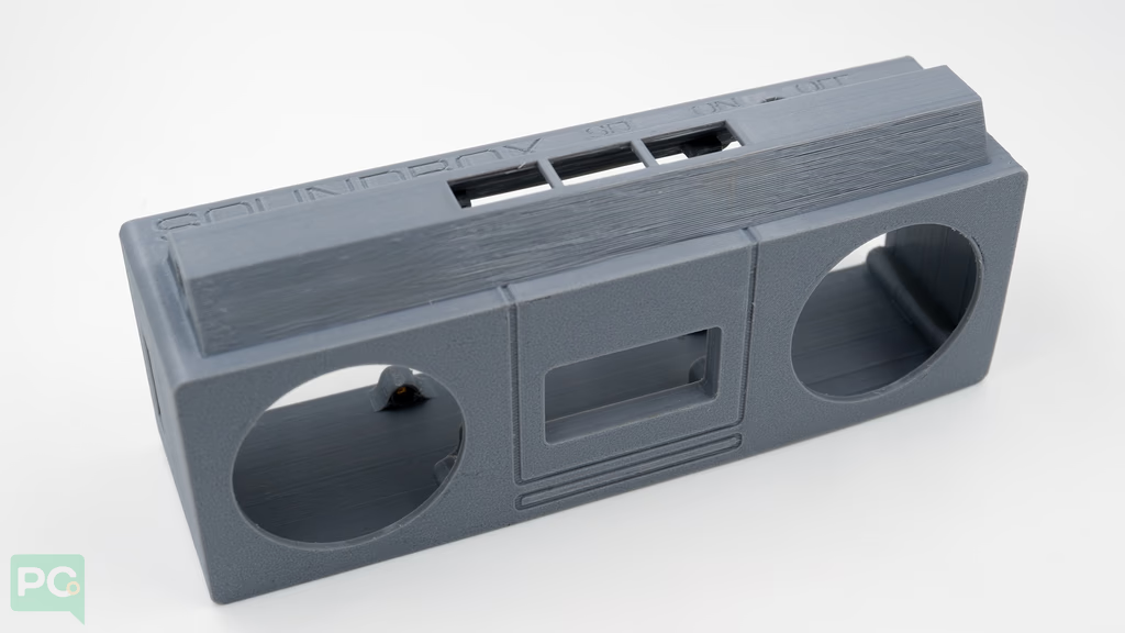
The SoundBox replicates the look and feel of a classic boombox, reimagined with modern components. Speaker and button placement mirror traditional stereo layouts.
Key Features
Audio Features
- MP3 / WAV Playback from SD card.
- Track Navigation: Next, Previous, Play, Pause.
- Non-blocking Audio Loop — keeps UI and buttons responsive.
- Track Metadata Handling: Displays song title and duration.
Display & UI Features
- High-contrast OLED UI with U8g2lib.
- Track Info Screen: Title, total time, play/pause state.
- Volume Display (0–100%).
- UI Navigation System (prev/next/select).
Controls
- 3 Physical Buttons (Prev, Play/Select, Next).
- Debounced Input using OneButton library.
- Volume control Range: 0–100%.
- UI & Player Sync — ensures displayed volume equals actual volume.
Build Guide
Build your SoundBox! Follow each step in order — wiring, flashing firmware, assembling the case, and first power-on tests.
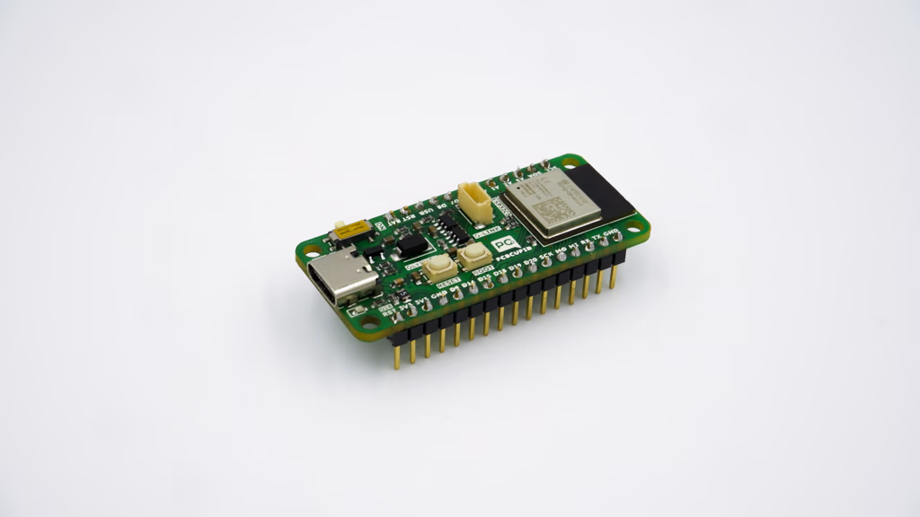
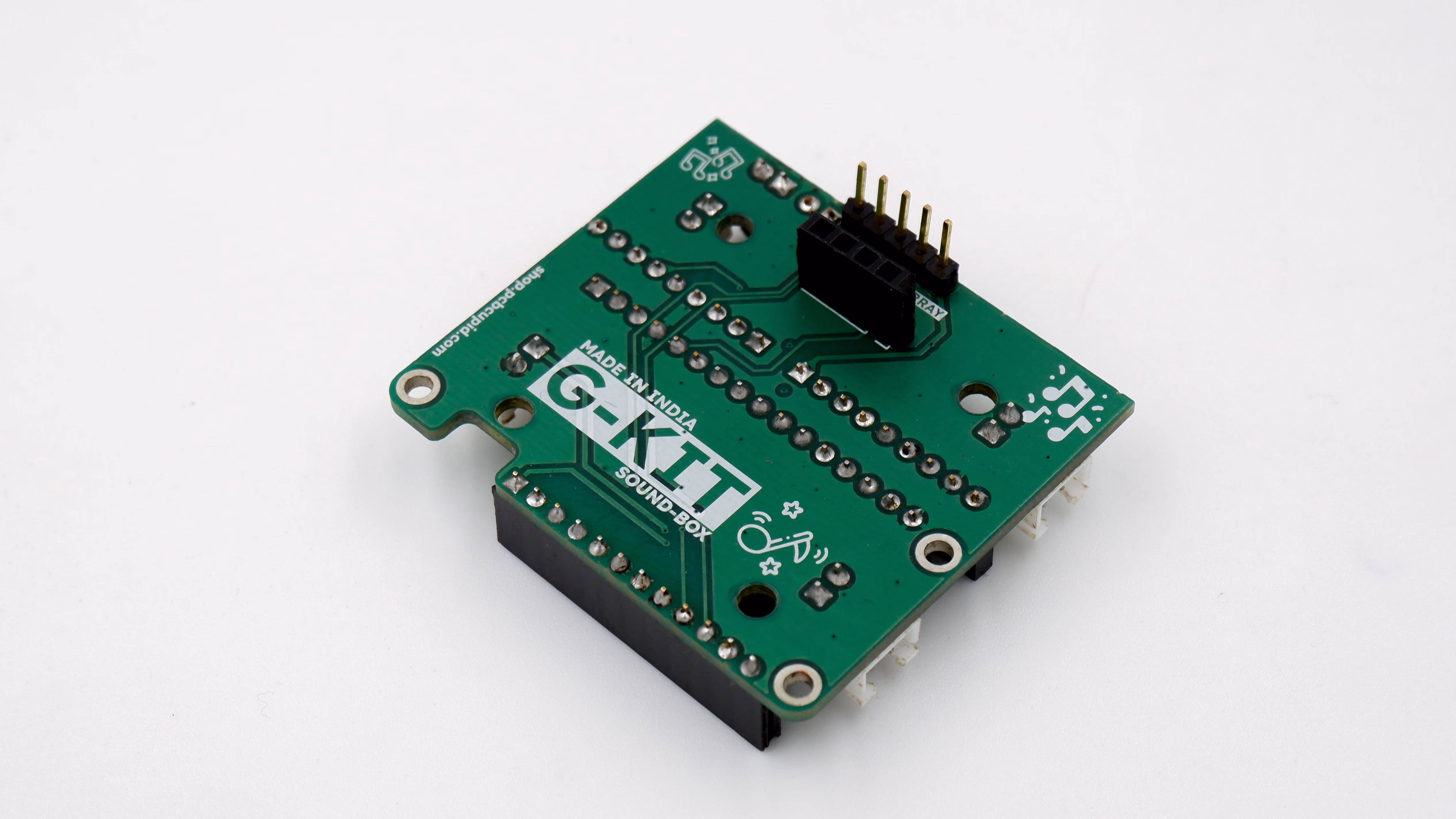
Step 1: Hardware Required
Get Your Electronics Ready
Get Your 3D Printed Parts Ready
Step 2: Pin Configuration
Table shows how each module connects to the controller (assuming Glyph C6) internally on the G-Kit base board.
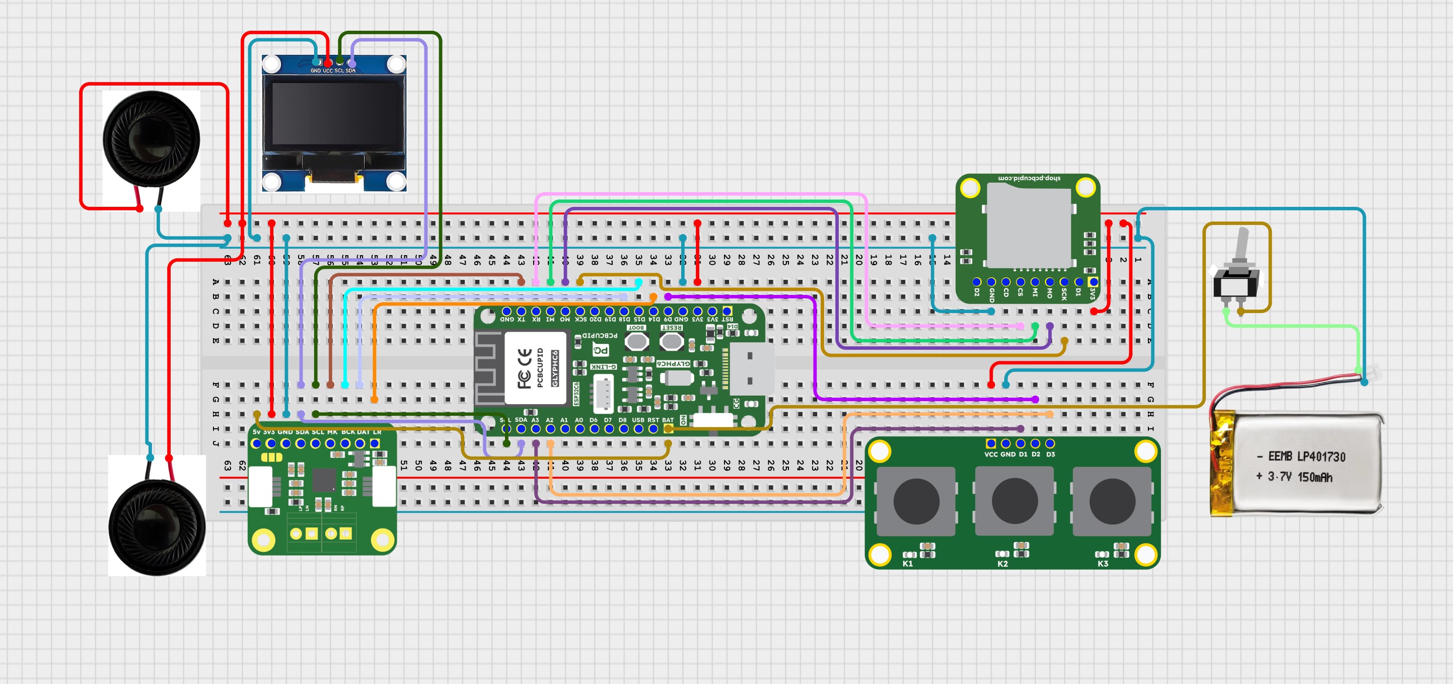
Step 3: Circuit Diagram
Follow the circuit below to build the SoundBox yourself with a breadboard and jumpers, without needing the PCB.
Step 4: Assembly
This section walks through complete assembly — from preparing components to final enclosure fitting.
Make sure to follow Step 5 and Step 6 for installation first. This ensures Glyph has necessary firmware to run SoundBox features and tests all electronics.
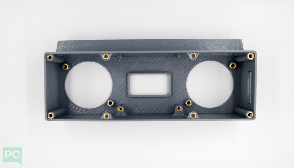
 The enclosure is printed to tight tolerances so components fit snugly. Before proceeding, check all mounting points and openings are clear of print residue.
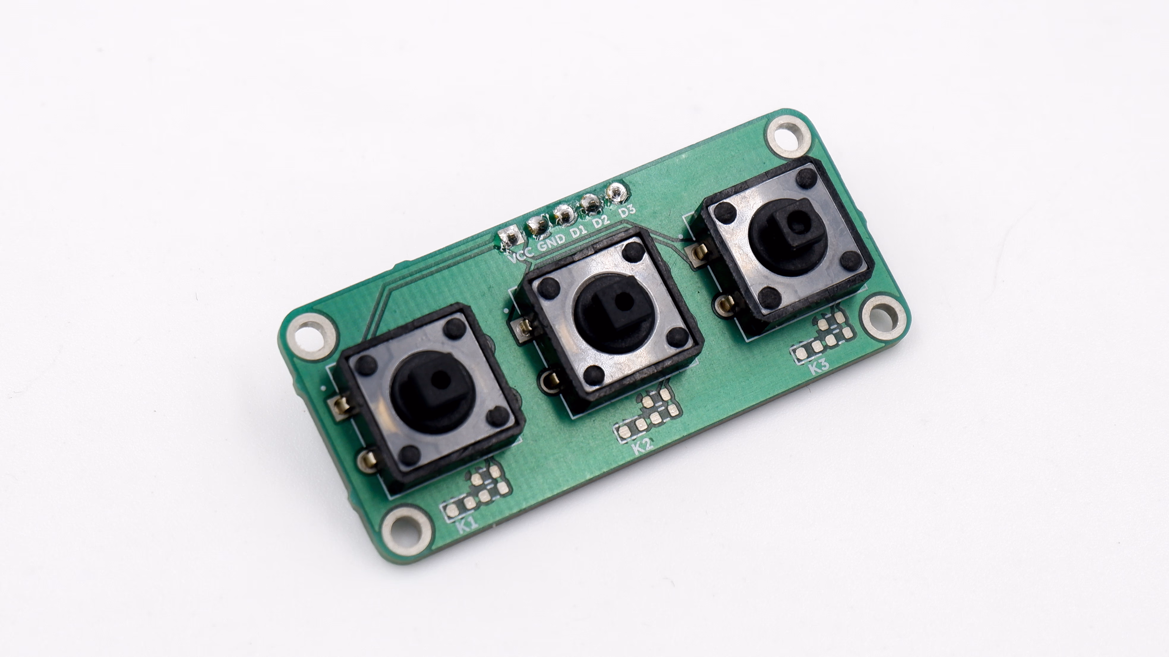
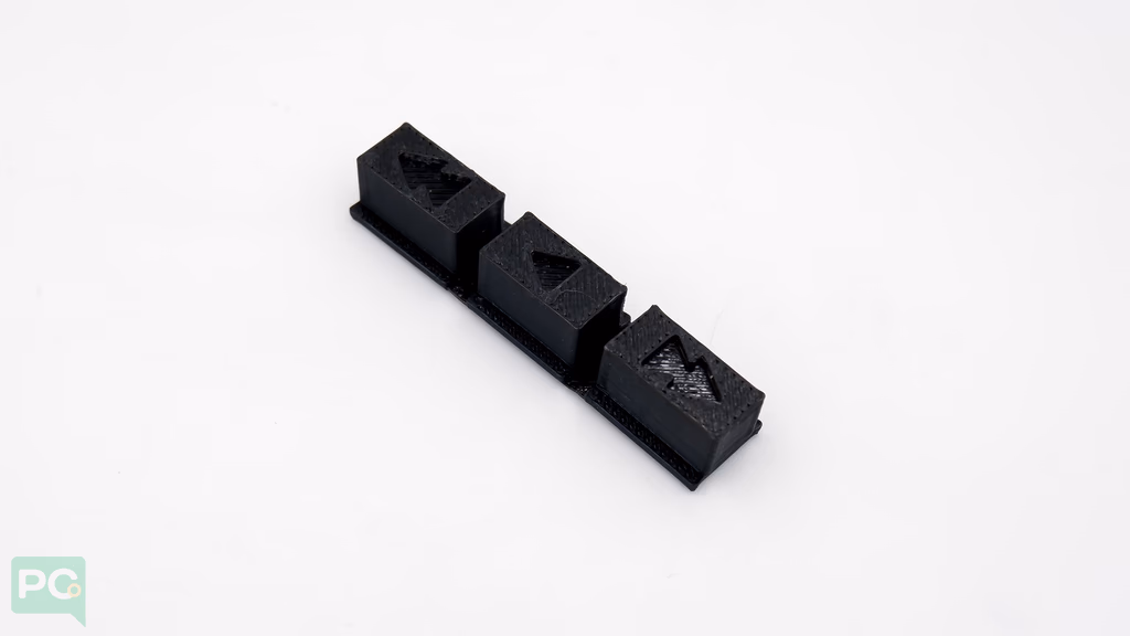
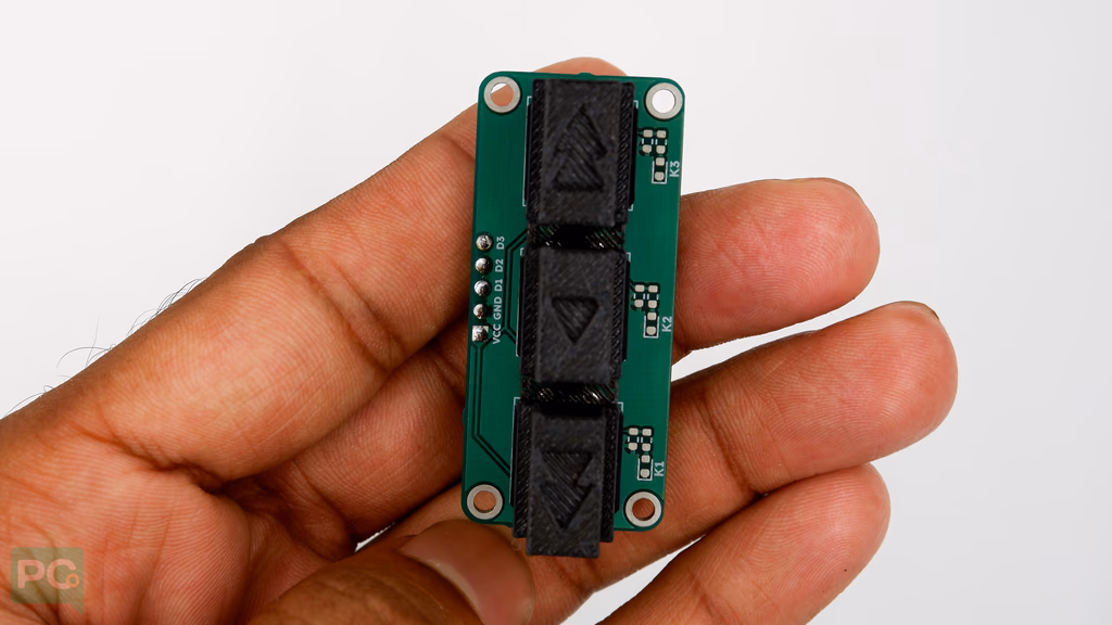
The button array with the 3D printed cap will snap-fit on the extrusion to hold the button array in place.
The enclosure is printed to tight tolerances so components fit snugly. Before proceeding, check all mounting points and openings are clear of print residue.
The button array with the 3D printed cap will snap-fit on the extrusion to hold the button array in place.
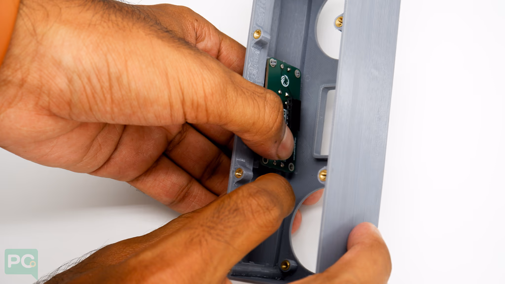
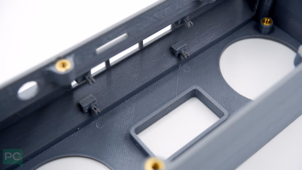 Align mounting holes on the button array to snap-fit points on the enclosure. Guide the button so the header faces away from the soundbox.
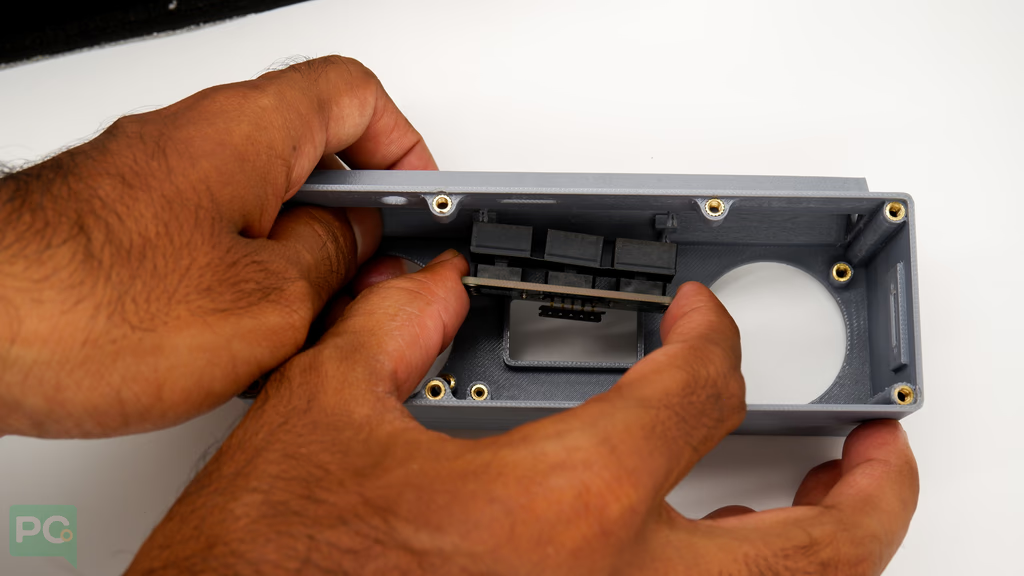 Apply pressure on one side until mounting holes snap fit, then the other side.
The snap-fit may be very tight and can hold the button array firmly — difficult to remove once in place.
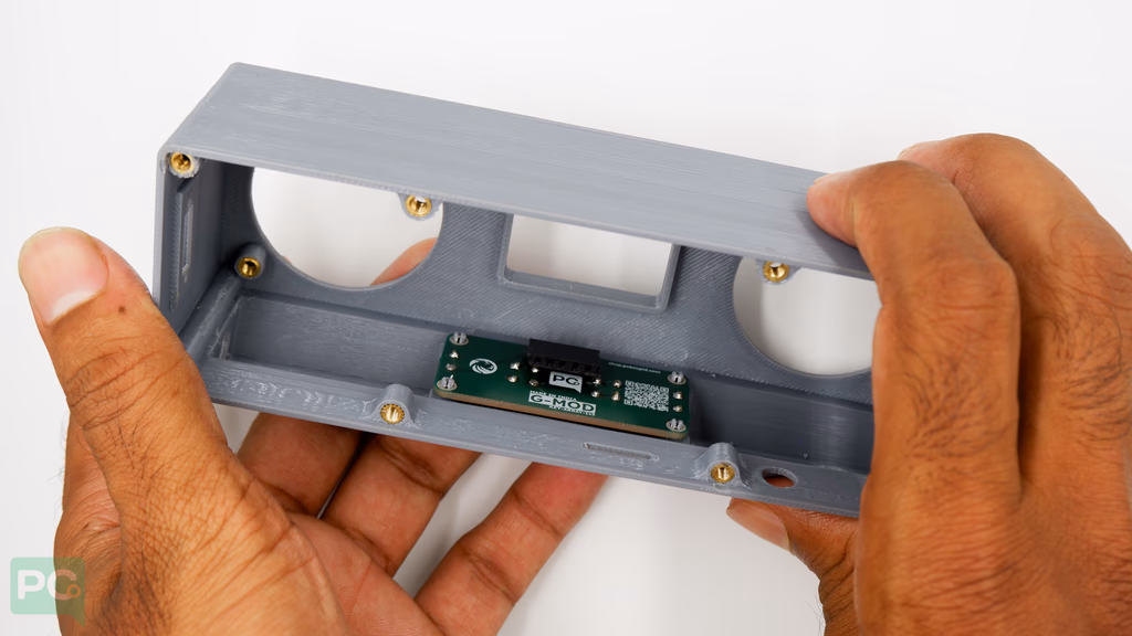
 Double-check the button fits well and header pin faces toward you. This is critical as the G-Kit base board will access it.
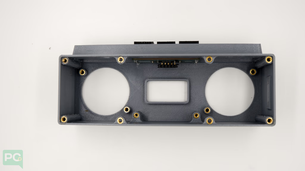
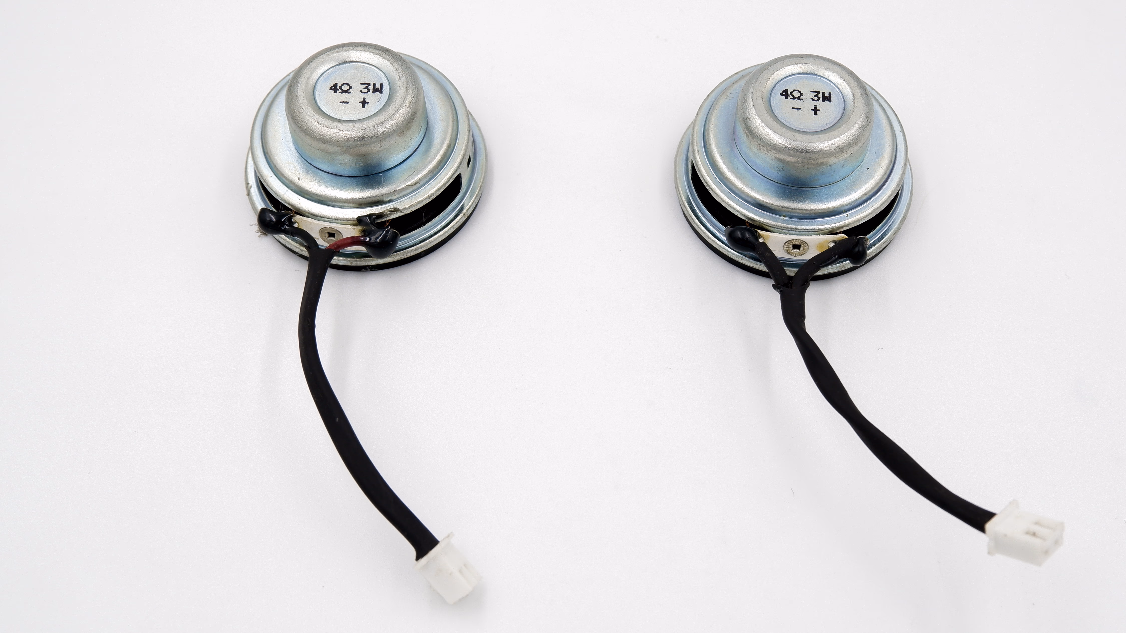
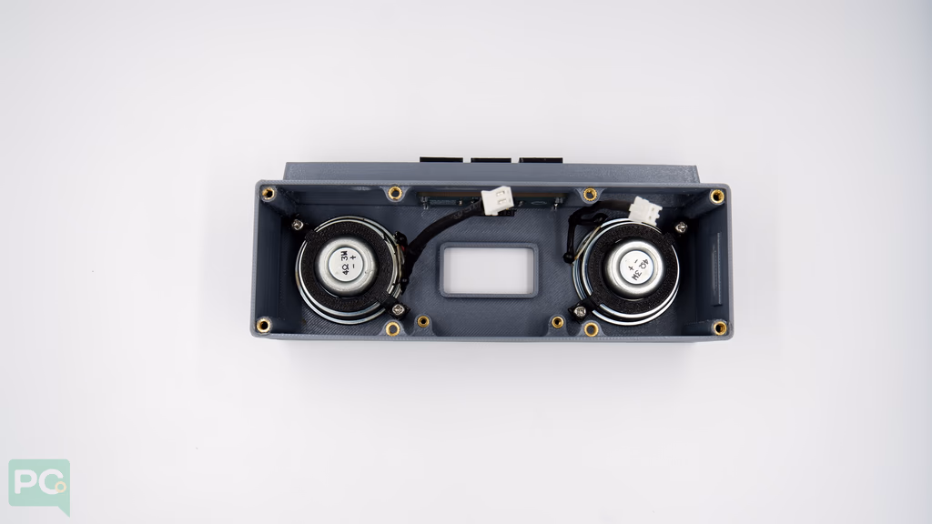
Installing the Speakers
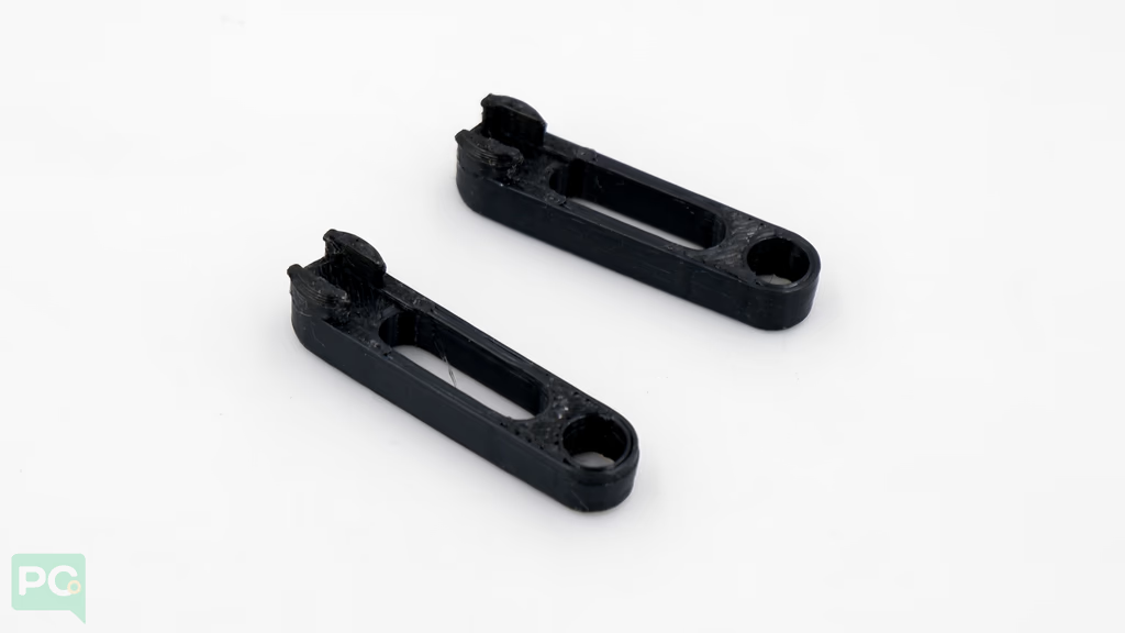
A 3D printed adapter holds the speaker to the enclosure.
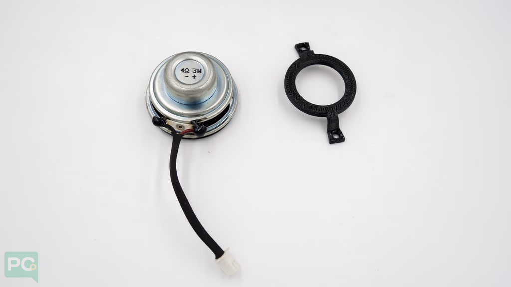
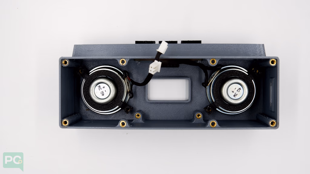
 Align the speaker adapter to mounting points on the enclosure. Repeat for both speakers.
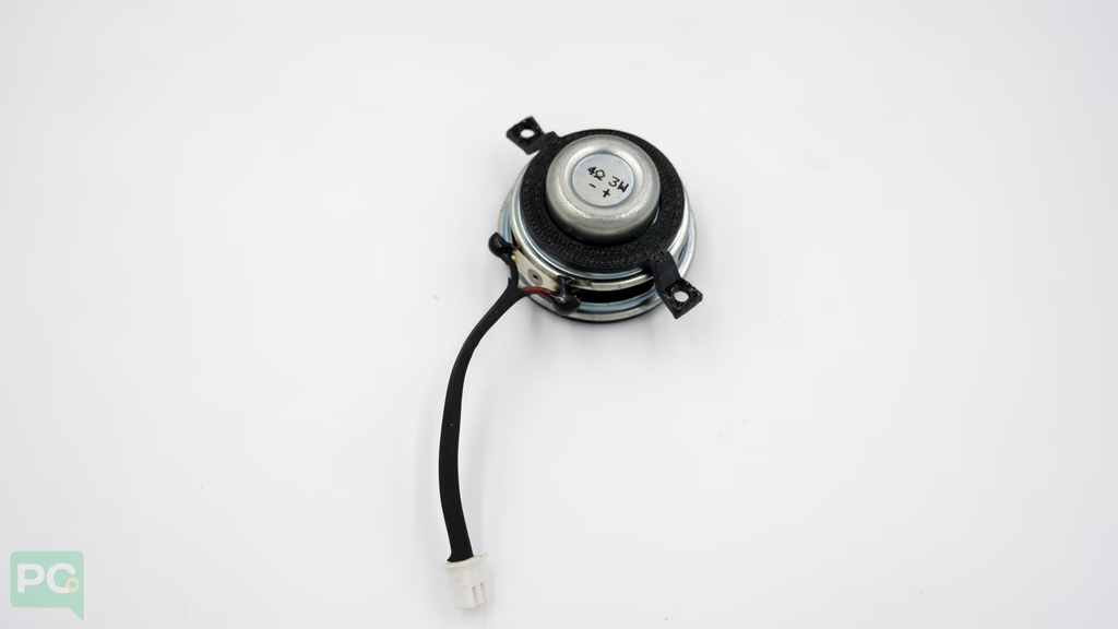
 Use M3 screws from the kit to fasten in place.
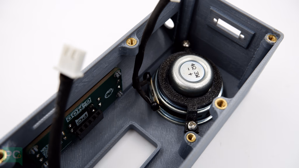 Ensure speaker wire connectors face toward the display for easier connection to the G-Kit base board.
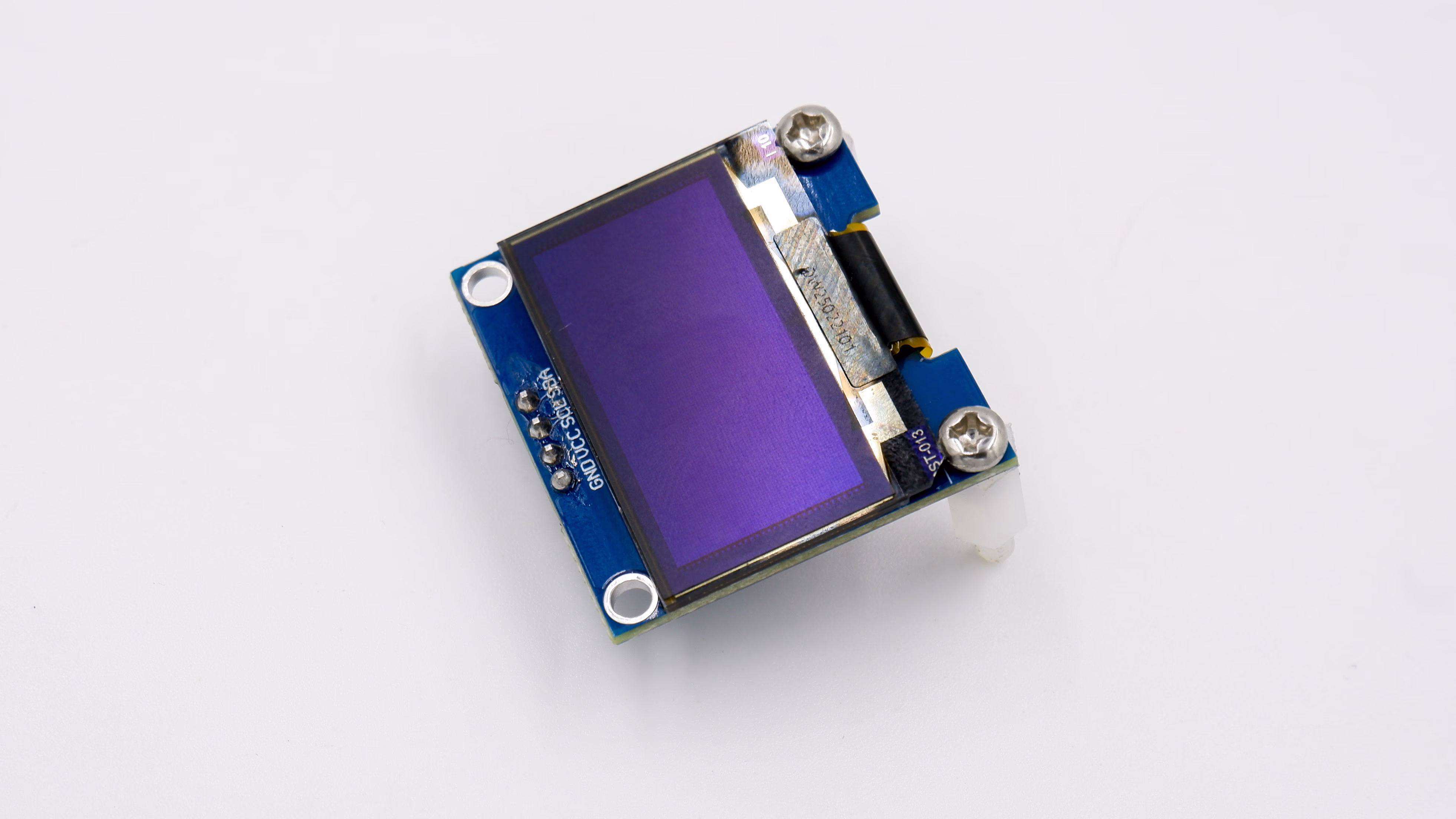
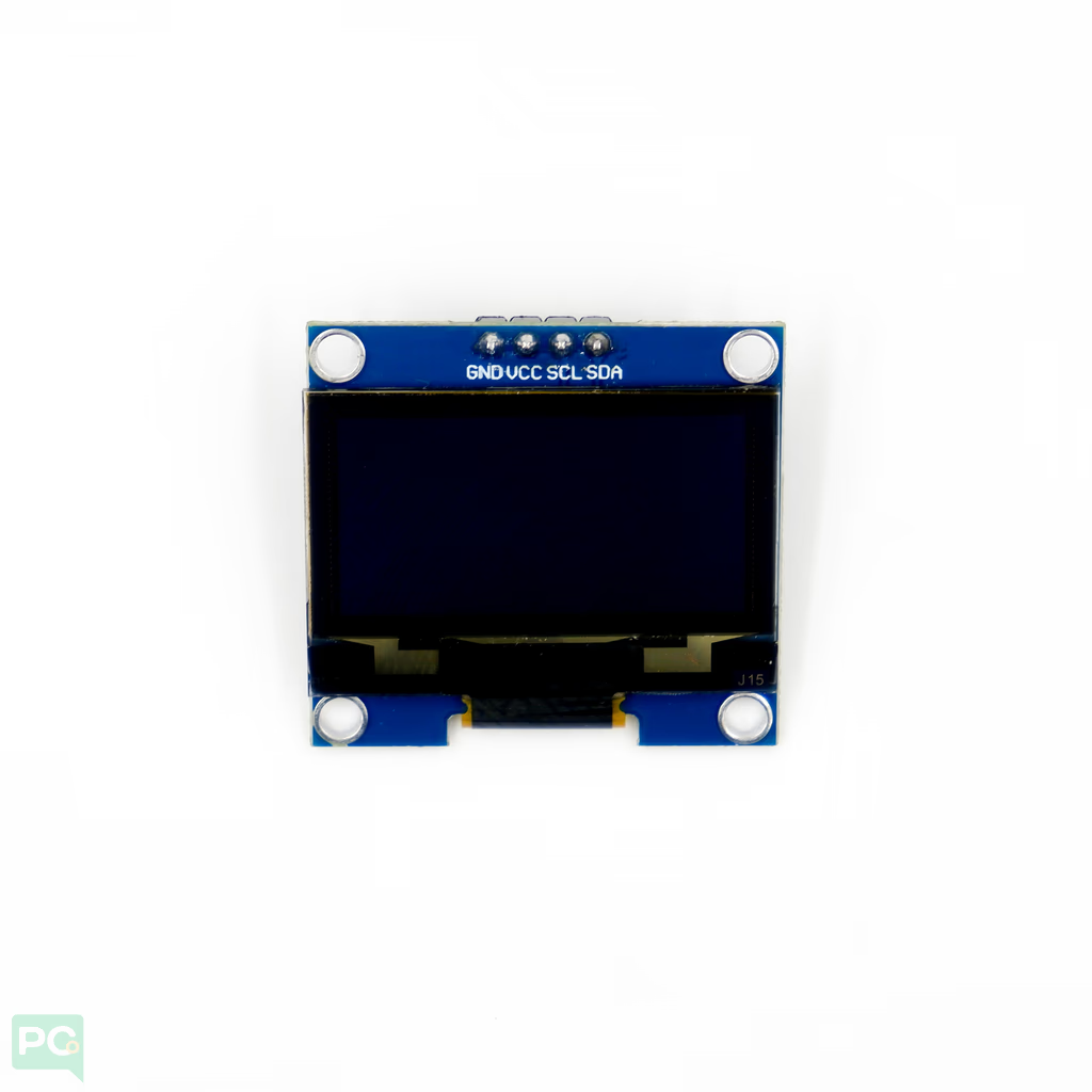
Installing the OLED
Assemble the OLED with 10mm nylon standoff to hold it firmly to the PCB.
Connect the OLED display to the base board.
Align the OLED so standoffs install correctly. No bolt needed on the other side — the base board and 3D printed parts provide support.
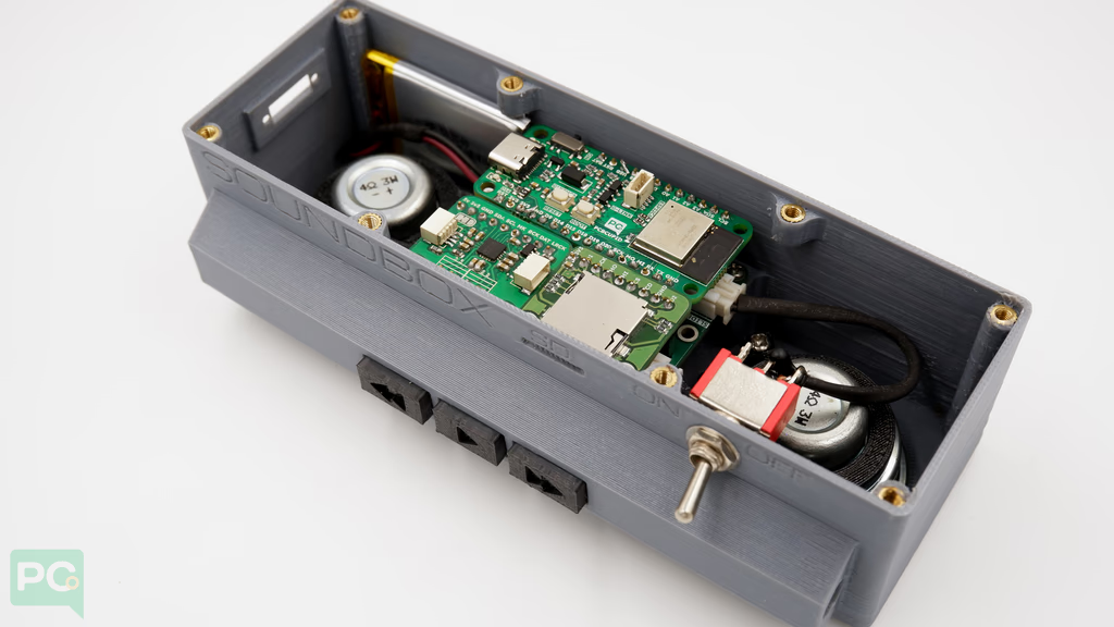
Installing the Base Board
Once the display is placed, position the base board into the enclosure.
 Ensure the header on top of the base board fits onto the button placed earlier.
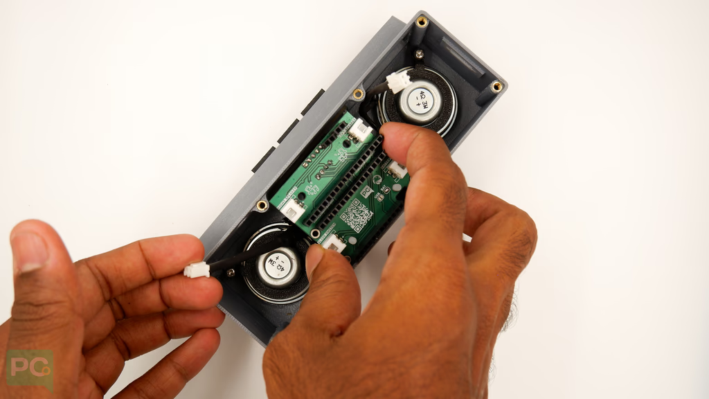 Fasten in place using M2.5mm bolts.
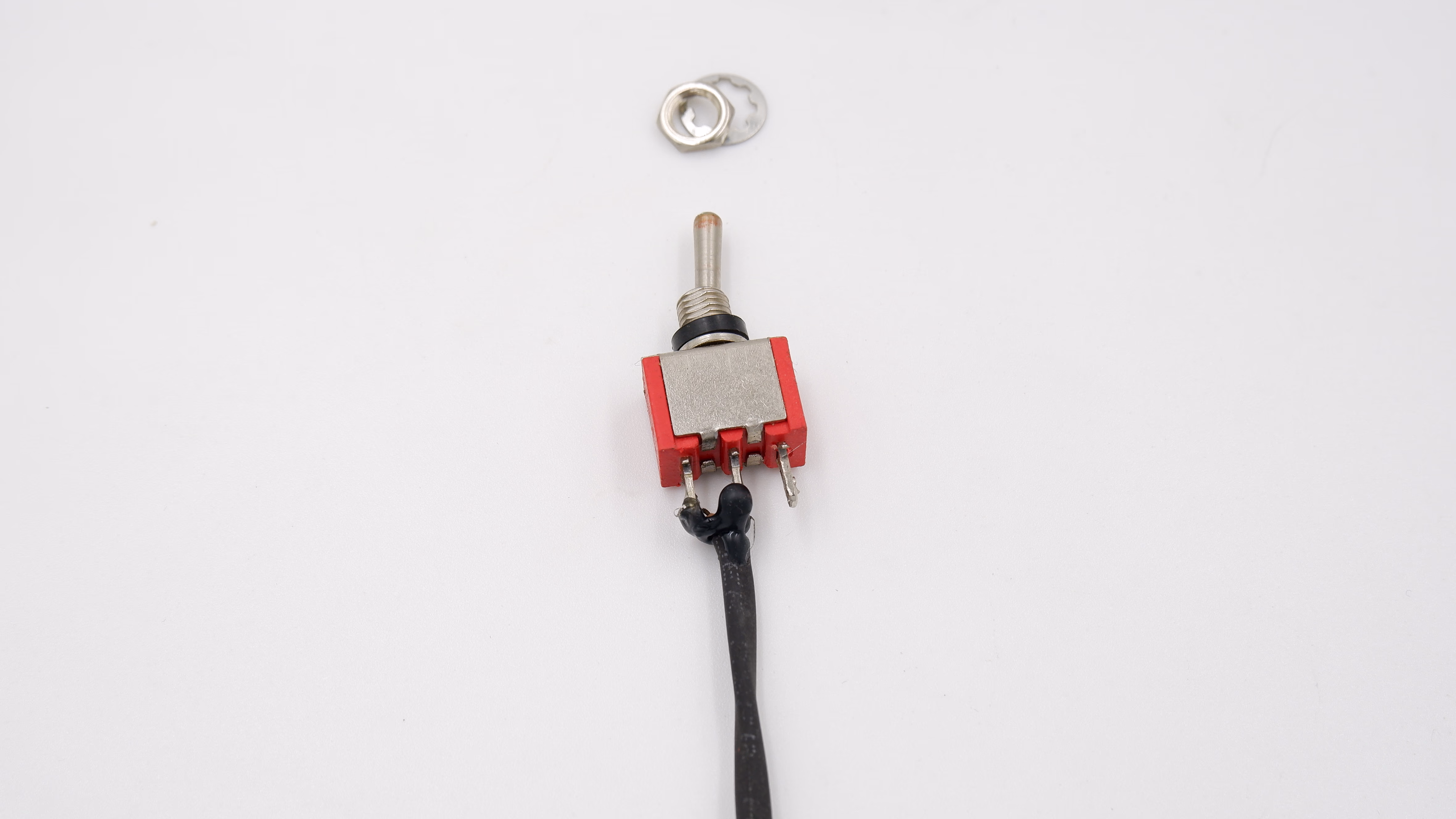
 Add the toggle button for power on/off.
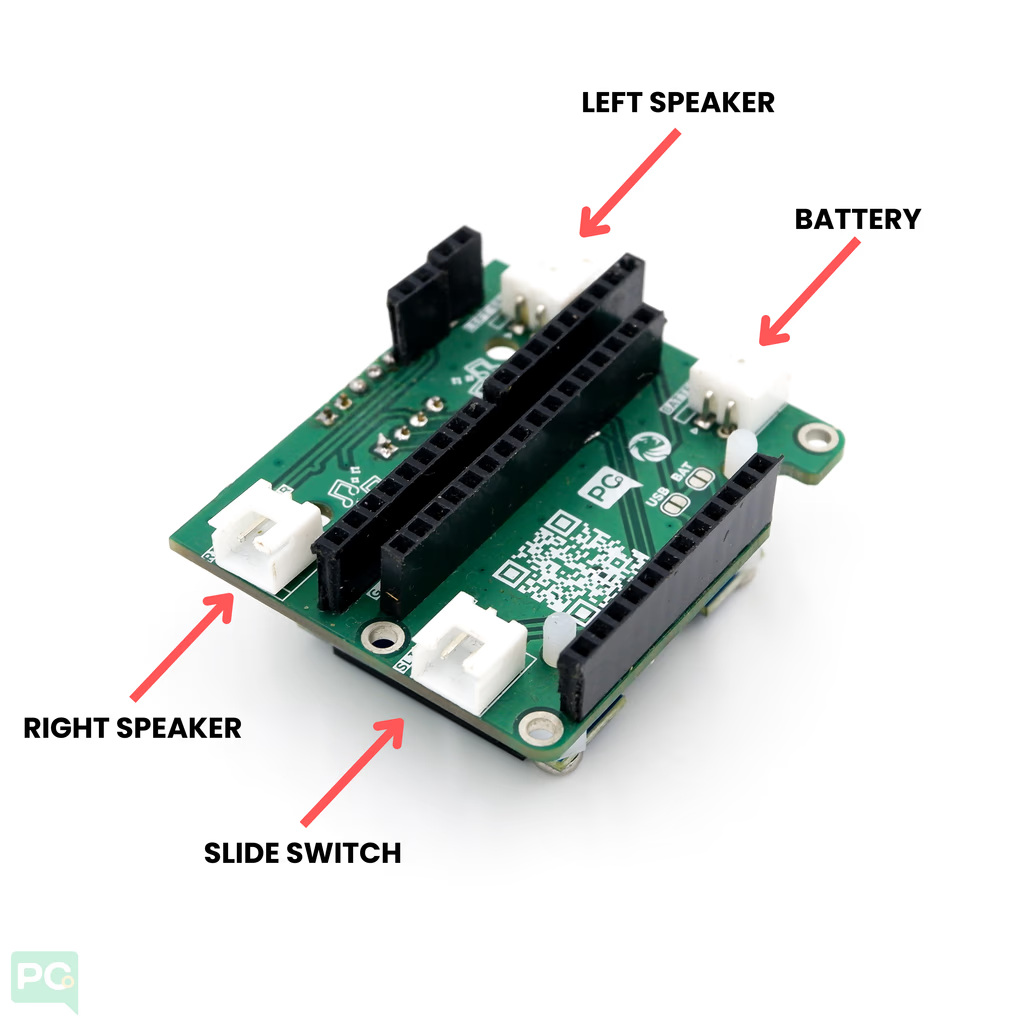
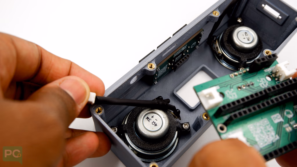
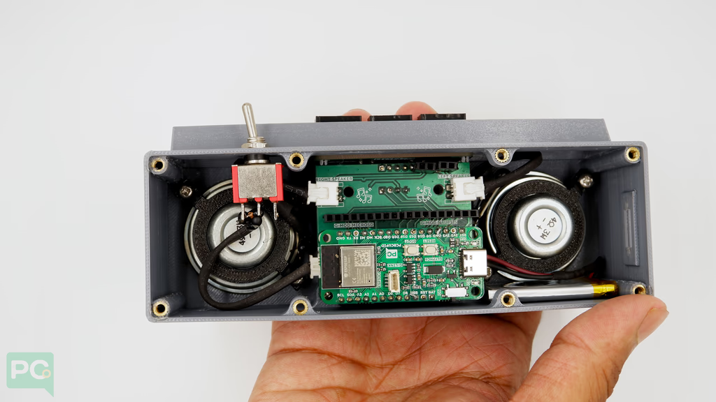
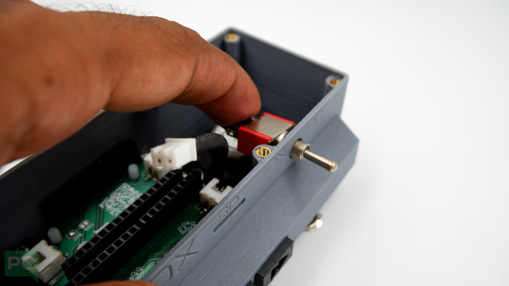 Connect speaker and toggle switch connectors to the base board.
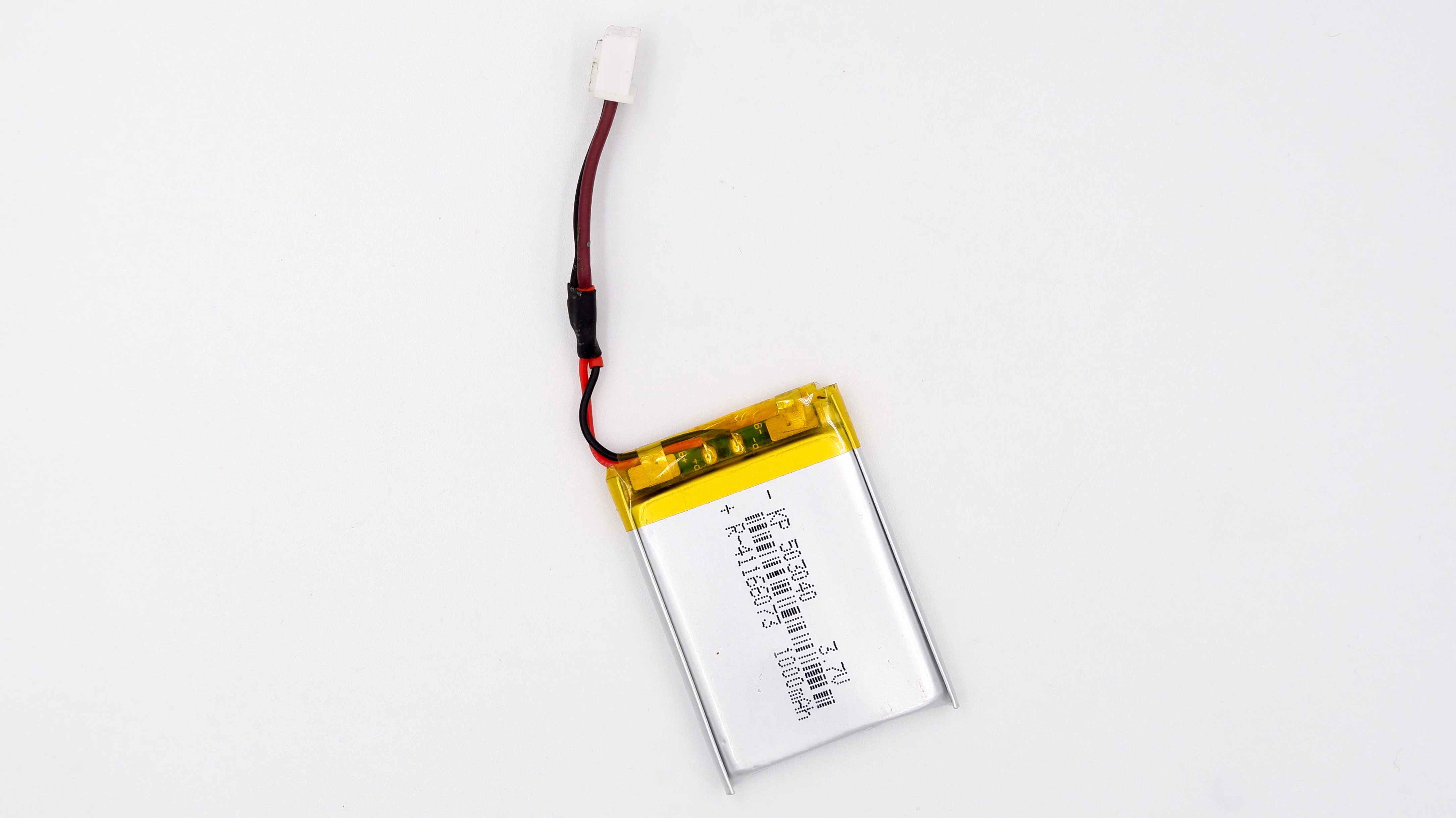
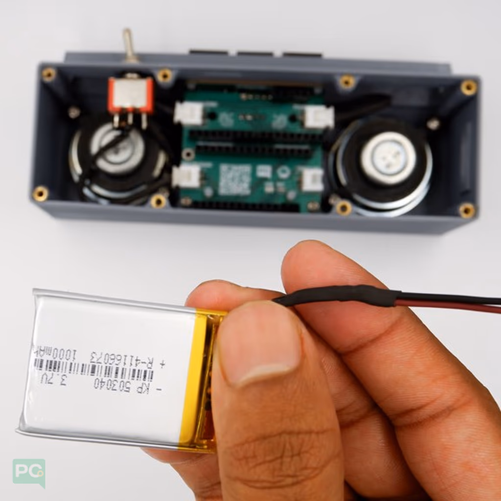
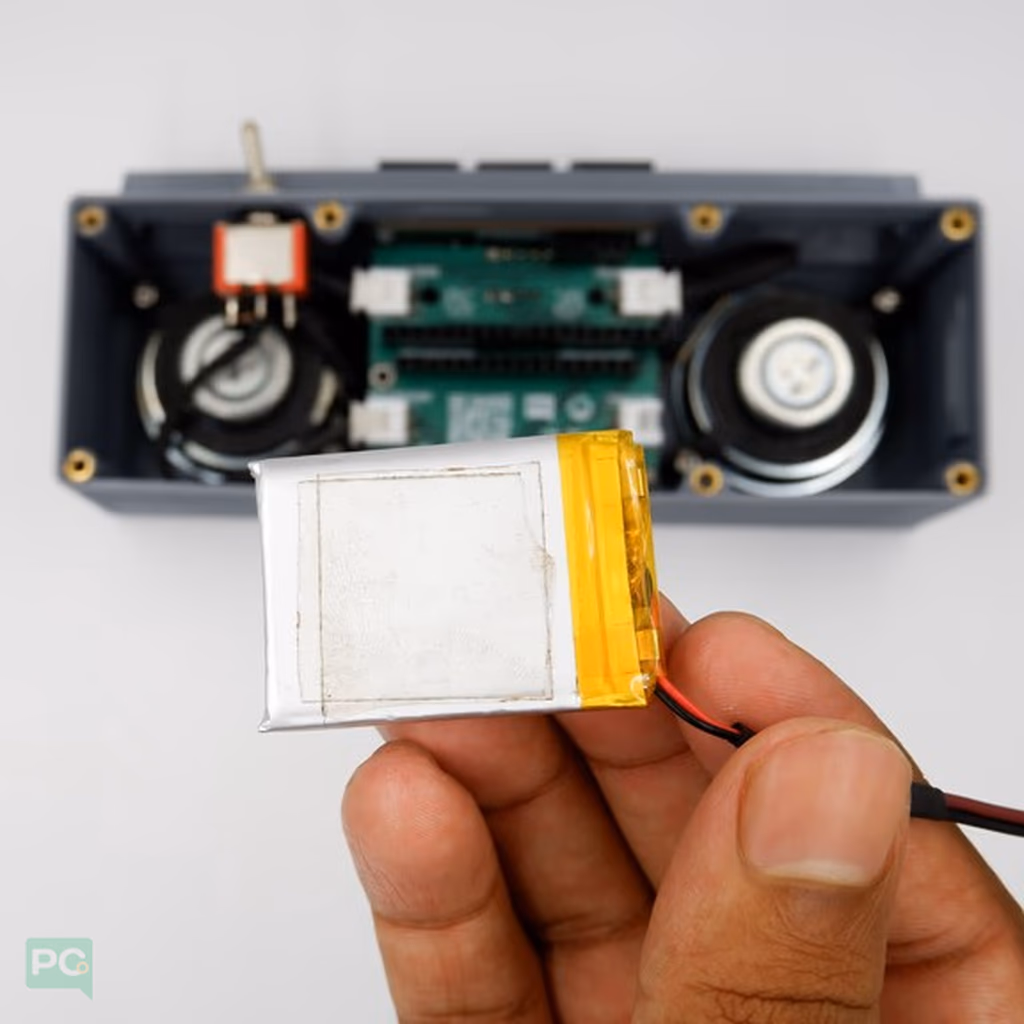
Apply double-sided tape to the battery to prevent movement inside the soundbox.
Place the battery as shown.
Connect speaker and toggle switch connectors to the base board.
Apply double-sided tape to the battery to prevent movement inside the soundbox.
Place the battery as shown.
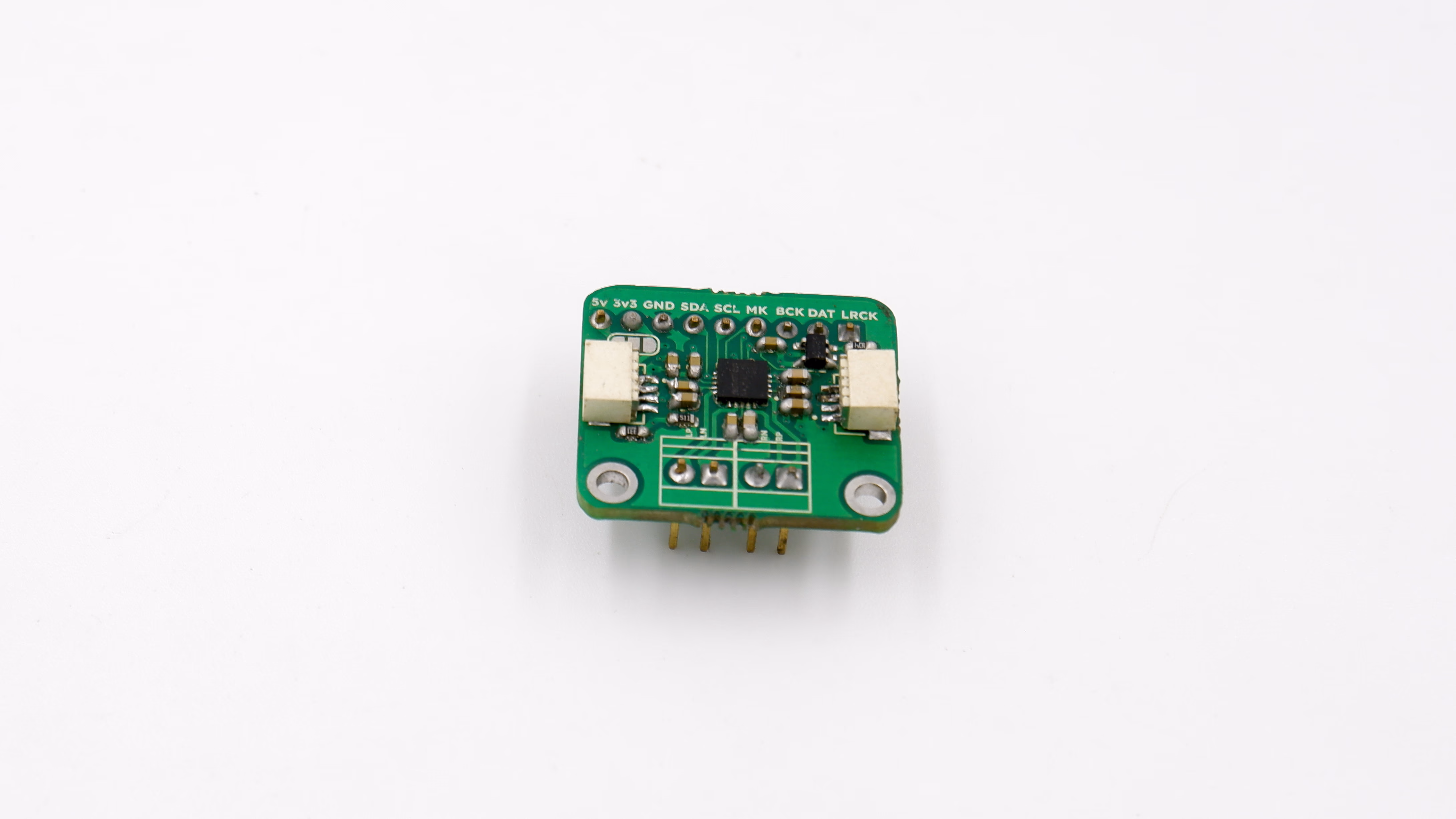
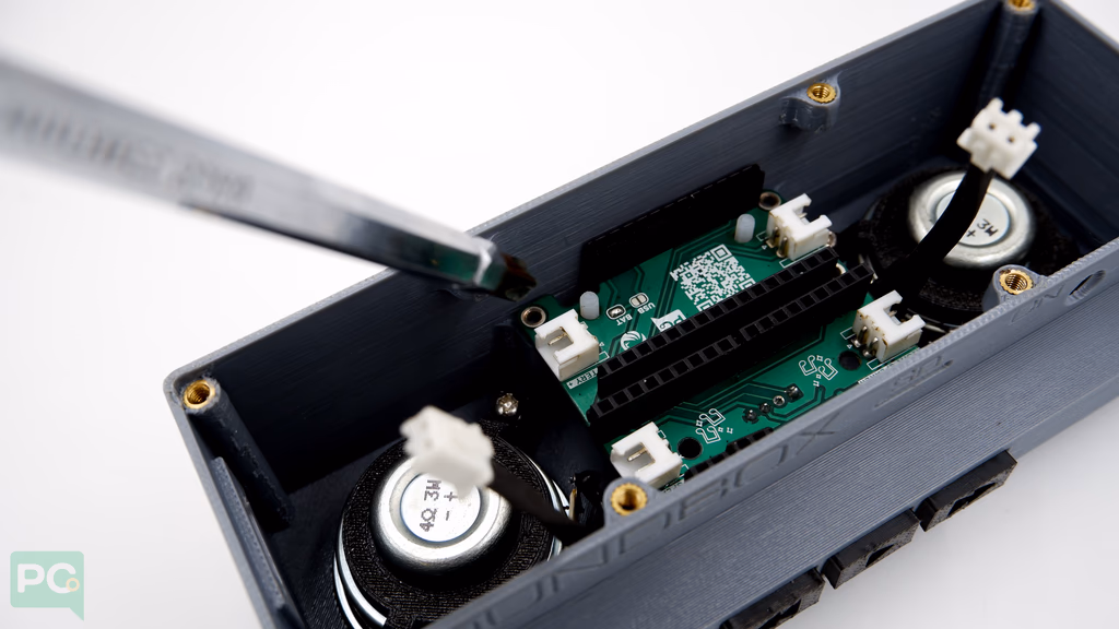
Installing the Audio CODEC
Place the audio codec module onto the G-Kit.
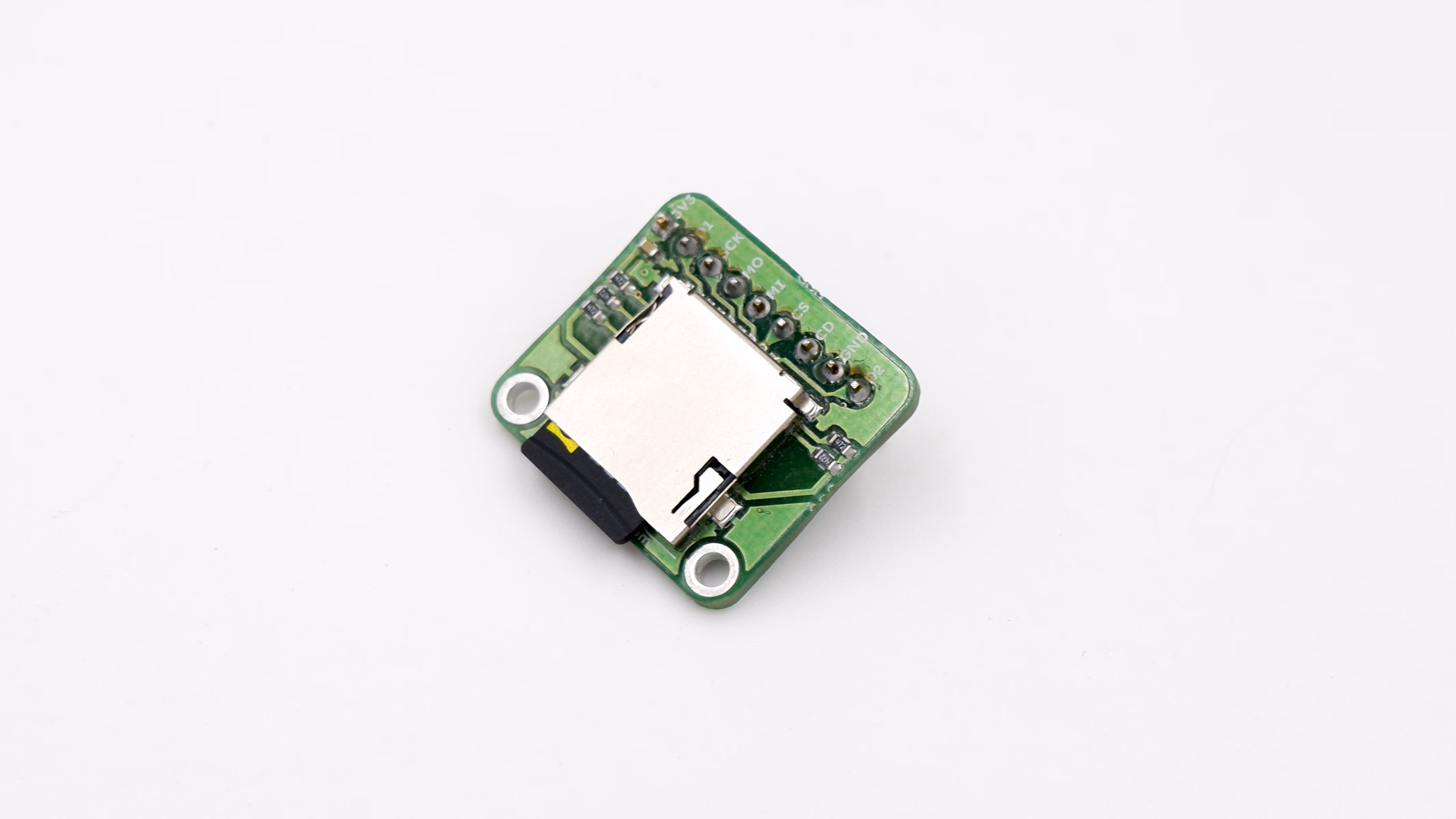
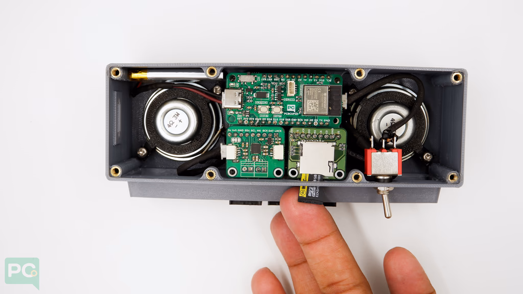
Installing the SD Card
Place an 8mm nylon spacer on the G-Kit PCB to support the GMOD-microSD.
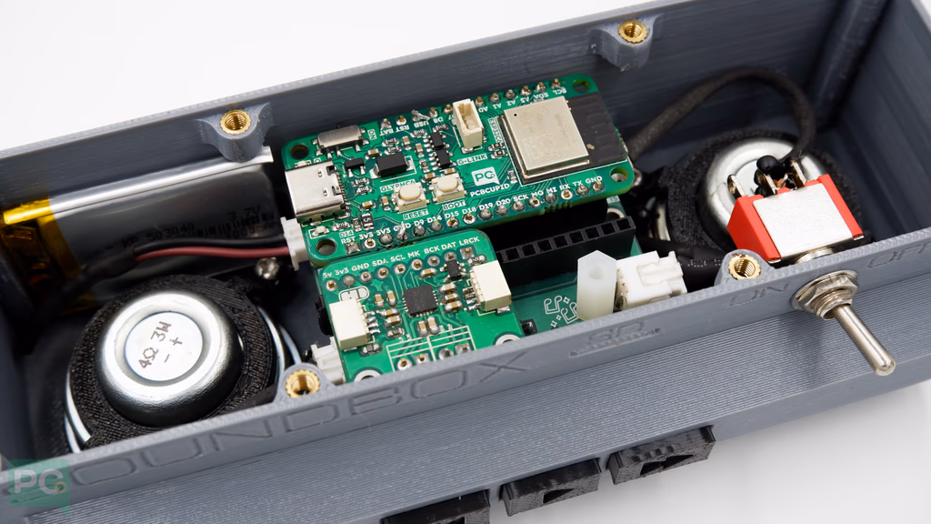 Place the GMOD-microSD card module and check the SD card is accessible outside the box.
 Insert the SD card with pre-loaded music into the SD-Card Module.
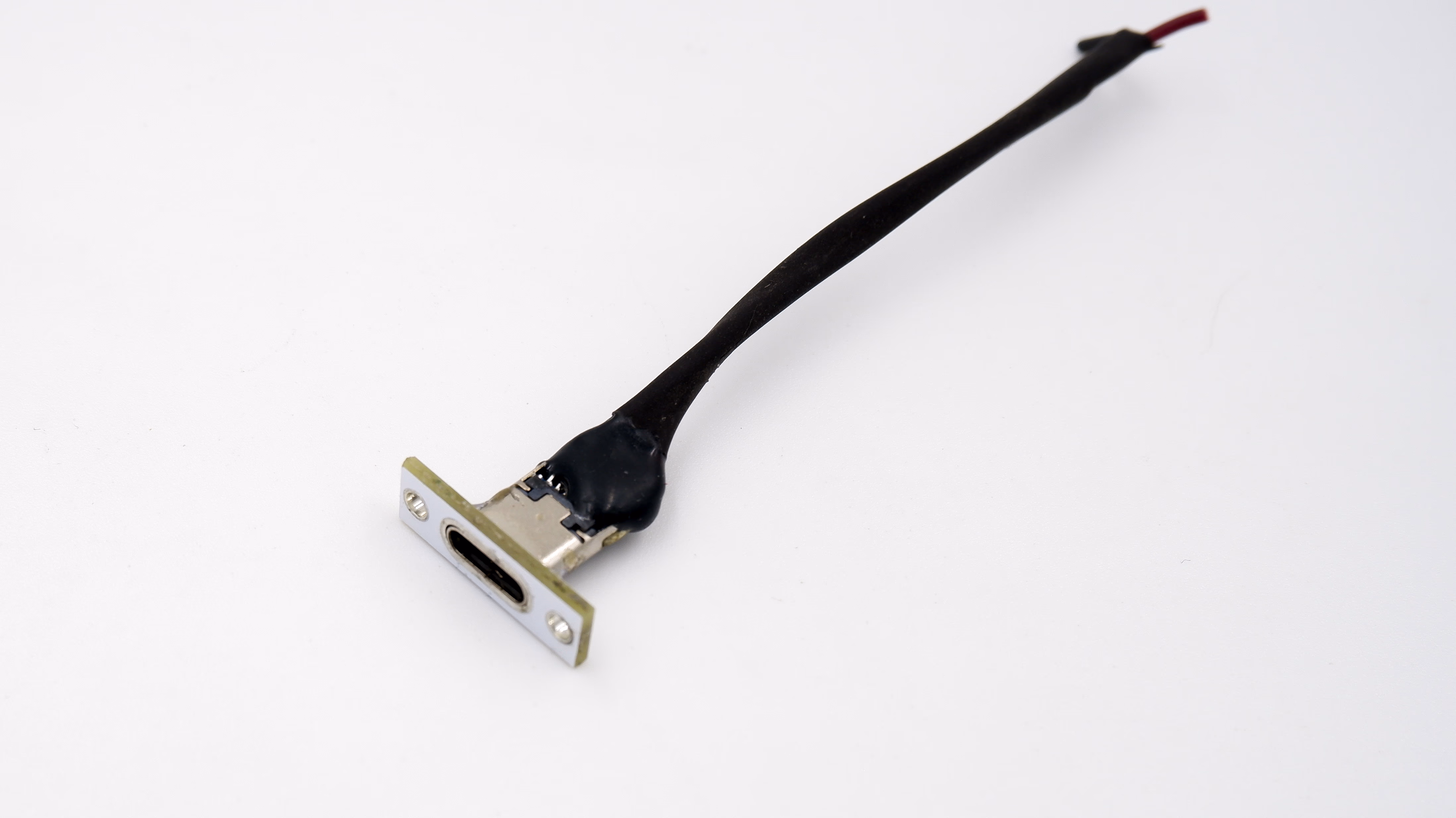
Installing the USB
Insert the Type C USB from outside.
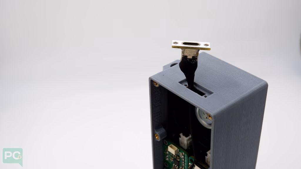 Ensure it fits snugly in the groove made for the C-port on the 3D model.
 Add 2mm bolts and nuts to the Type C USB port to hold it together with the 3D model.
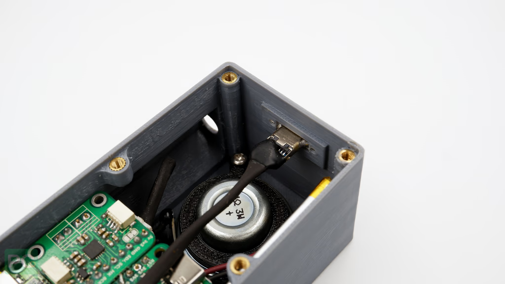 Solder the wires to the GLYPH board (Black → GND, Red → USB).
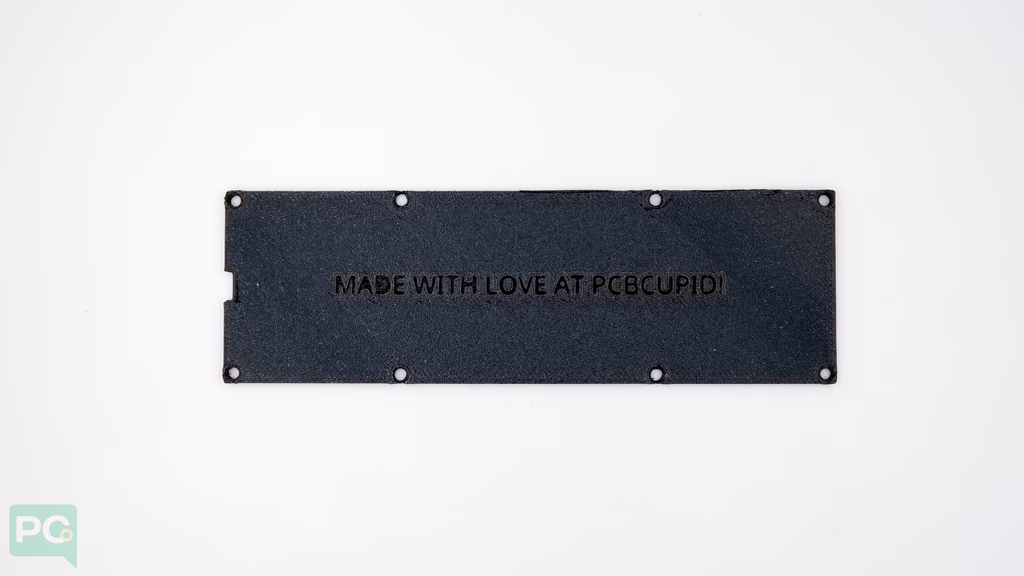
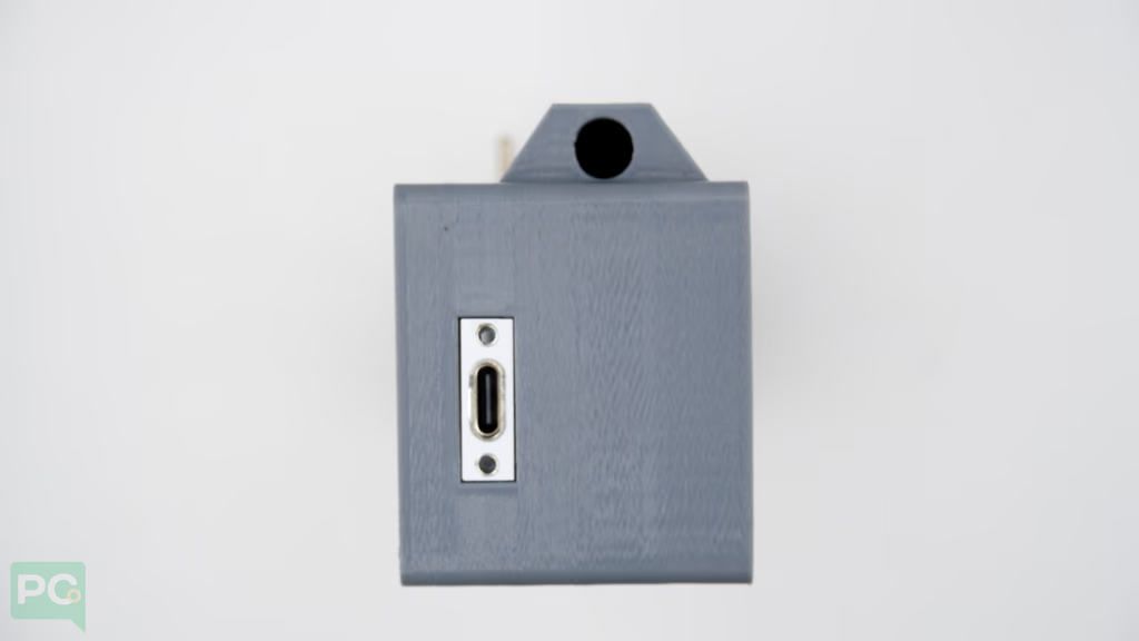
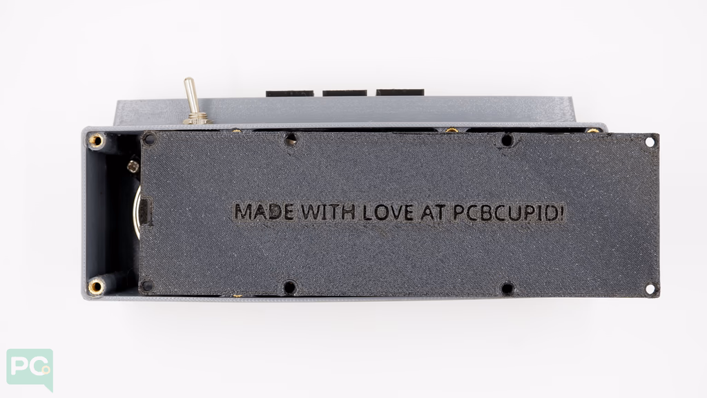
 Add the back panel to finish.
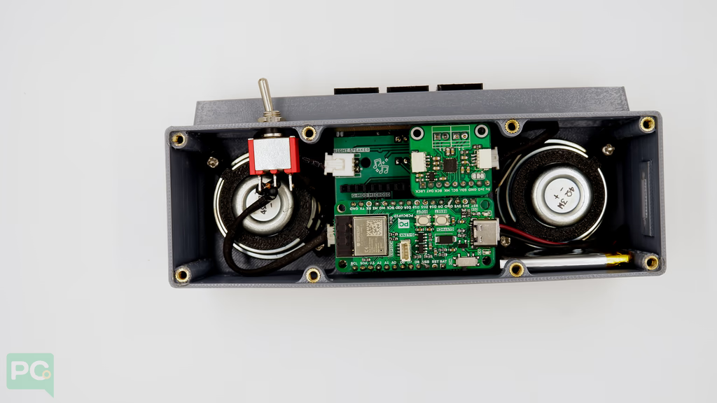
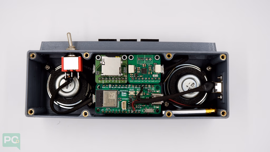
 SoundBox after full assembly:
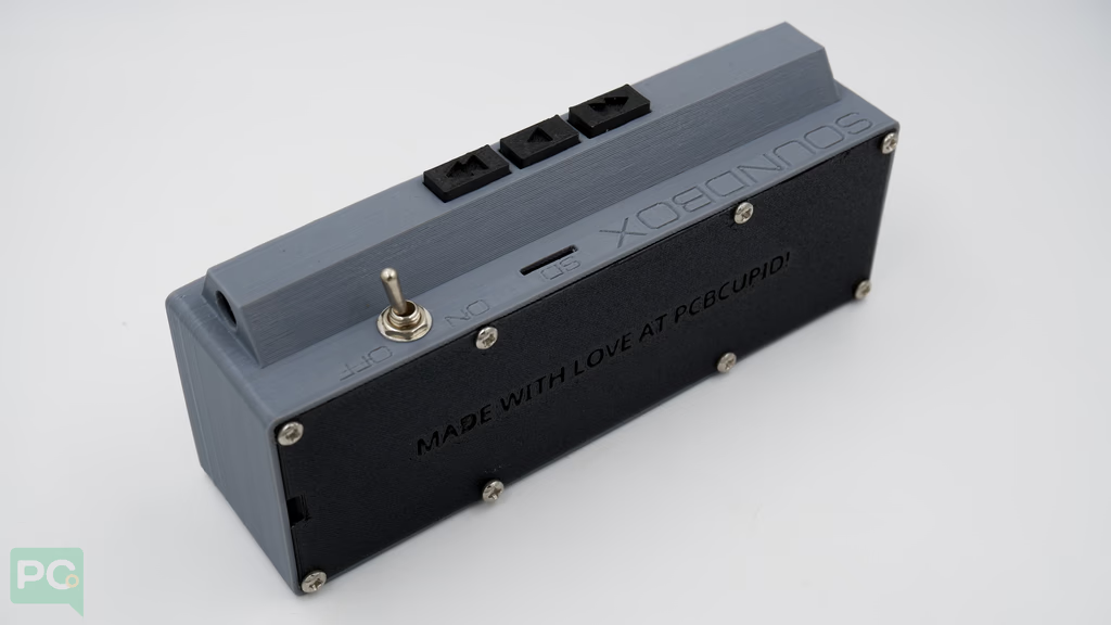 Toggle the switch to start!
 After a few seconds the SoundBox boots up.
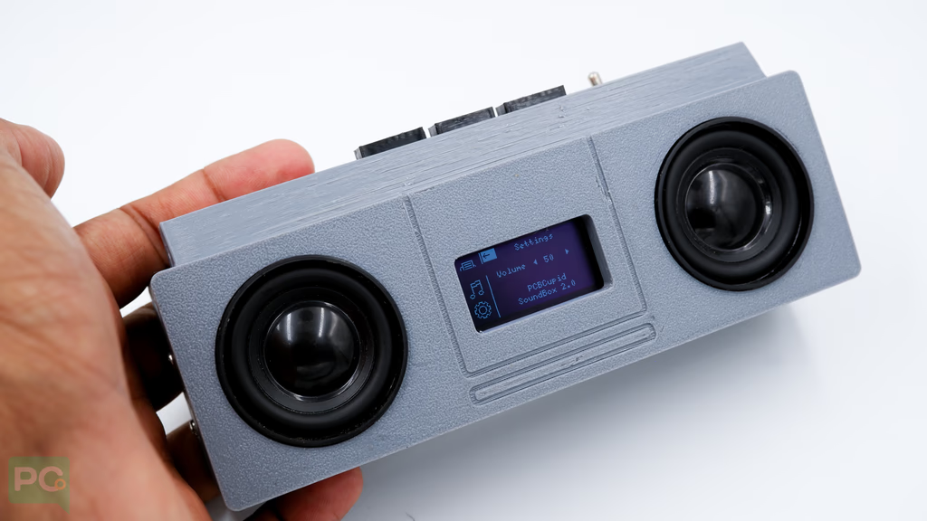 Navigate and select songs to play.
Step 5: Code Setup
- Open Arduino IDE.
- Make sure to install required libraries.
- Copy and paste the following code into the Arduino IDE.
The code is broken down into multiple files. Download from our GitHub Repo.
Step 6: Upload the Code
-
Connect the Board — Connect your GLYPH board to your computer.
-
Select the Board and Port
Tools > Board > esp32 > Pcbcupid GLYPH C6
For Pcbcupid Glyph C6 to appear under Tools > Board > esp32, the esp32 board version installed in Arduino IDE should be ≥ 3.1.0.
Tools > Port — select the port connected to your GLYPH.Tools > USB CDC on Boot — Enabled
If USB CDC on BOOT is not enabled, you won’t see serial data on Arduino IDE.
- Upload the Code — Click the upload button (➡️) or use
CRTL + U in Arduino IDE.
Step 7: Observe the Output
Expected Visual + Audio Behavior:
- Music playback from SD card over I2S DAC.
- OLED UI with track title, duration, elapsed time, volume.
- Buttons for control (Prev / Play / Next / Vol Up / Vol Down).
- UI updates in sync with audio (progress bar, elapsed time).