> ## Documentation Index
> Fetch the complete documentation index at: https://learn.pcbcupid.com/llms.txt
> Use this file to discover all available pages before exploring further.
> Set up Zigbee communication between a Glyph ESP32-C6 coordinator and ESP32-H2 end device in the Arduino IDE to remotely blink an LED over the air.
# Arduino Zigbee Blink: C6 to H2
# Zigbee + GLYPH with Arduino IDE
## Step 1: Hardware Required
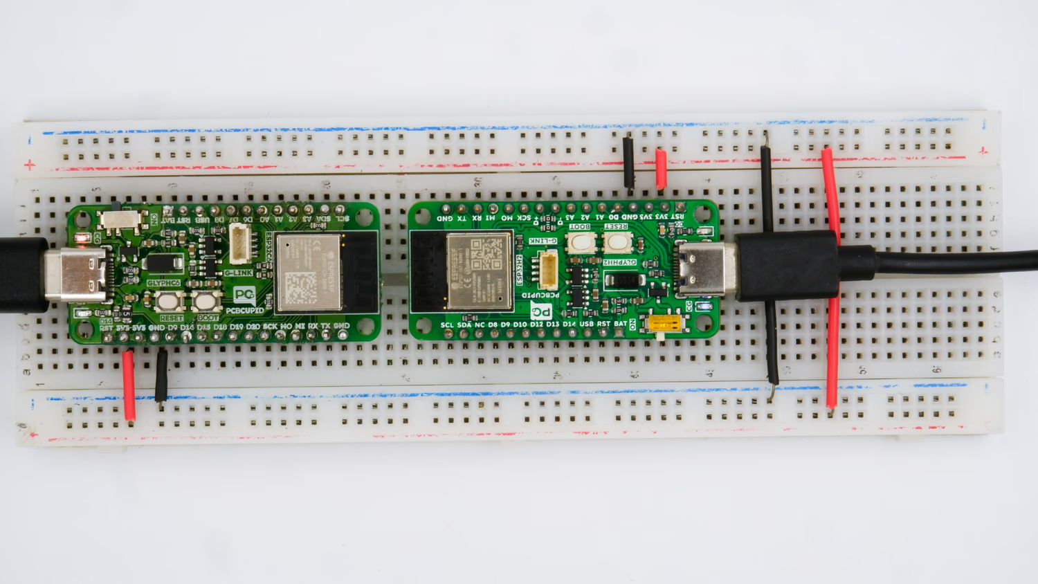
1. One client device \[[Glyph C6](https://shop.pcbcupid.com/product/gd002/) OR [GLYPH H2](https://shop.pcbcupid.com/product/gd003/)]
2. One Server device \[[Glyph C6](https://shop.pcbcupid.com/product/gd002/) OR [GLYPH H2](https://shop.pcbcupid.com/product/gd003/)]
## Step 2: Circuit Diagram
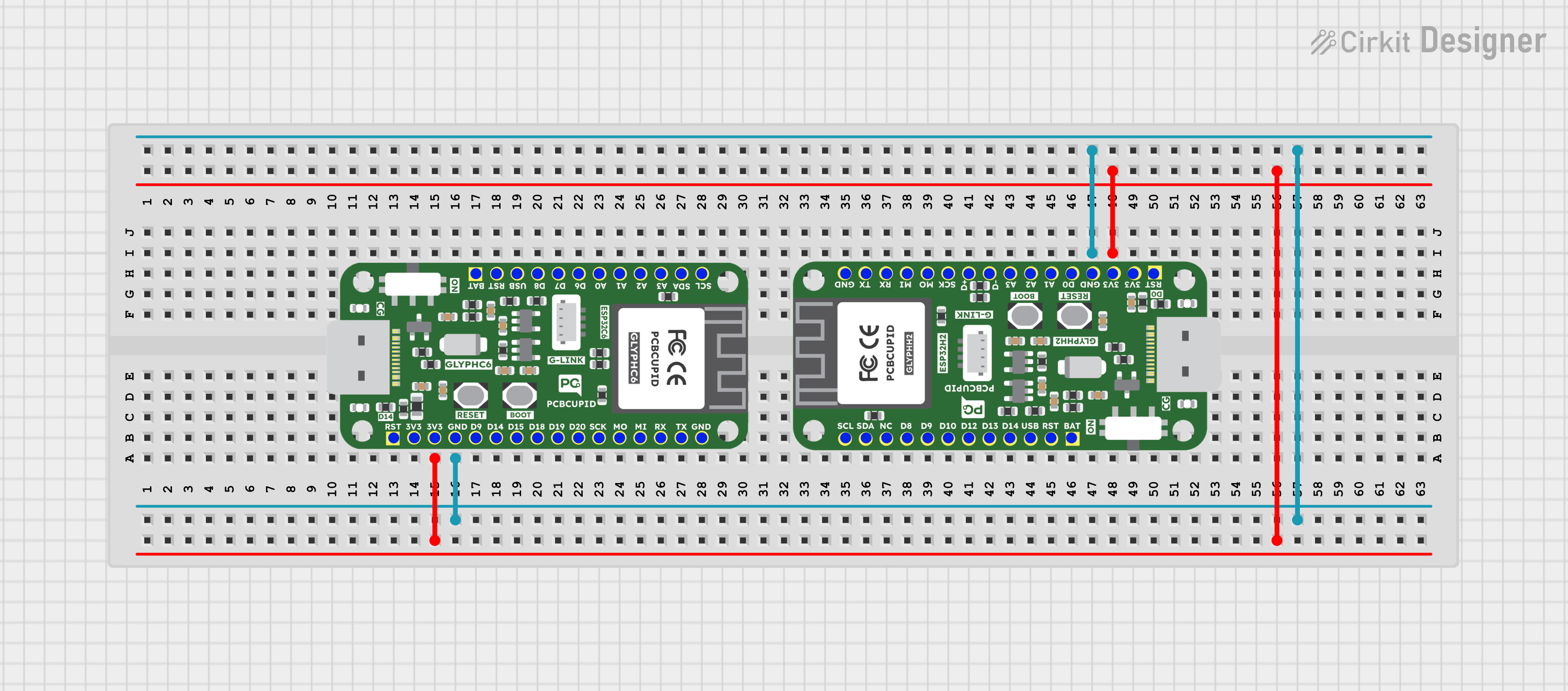
## Step 3A: Prerequisites to achieve Zigbee communication
1. Open **Arduino IDE**.
Make sure to update your Arduino IDE to a version greater than 3.1.0 Download and install it from the Arduino website.
Recommended always download the latest version
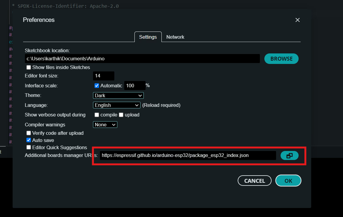
* Go to **File > Preferences**.
* In the **Additional Boards Manager URLs field**, add:
`https://espressif.github.io/arduino-esp32/package_esp32_index.json`
2. **ESP32 Board Definitions**: Install ESP32 board support in the Arduino IDE.
* Go to **Tools > Board > Boards Manager**.
* Search for “ESP32” and install **ESP32 by Espressif Systems and set it to the latest version**
## Step 3B: Setup Co-Ordinator
Plug-in your GLYPH development board, it can either be GLYPH C6 or GLYPH H2. We'll setup any of this board as coordinator/router device. Thus, the coordinator device becomes the switch to control the LED on other device.
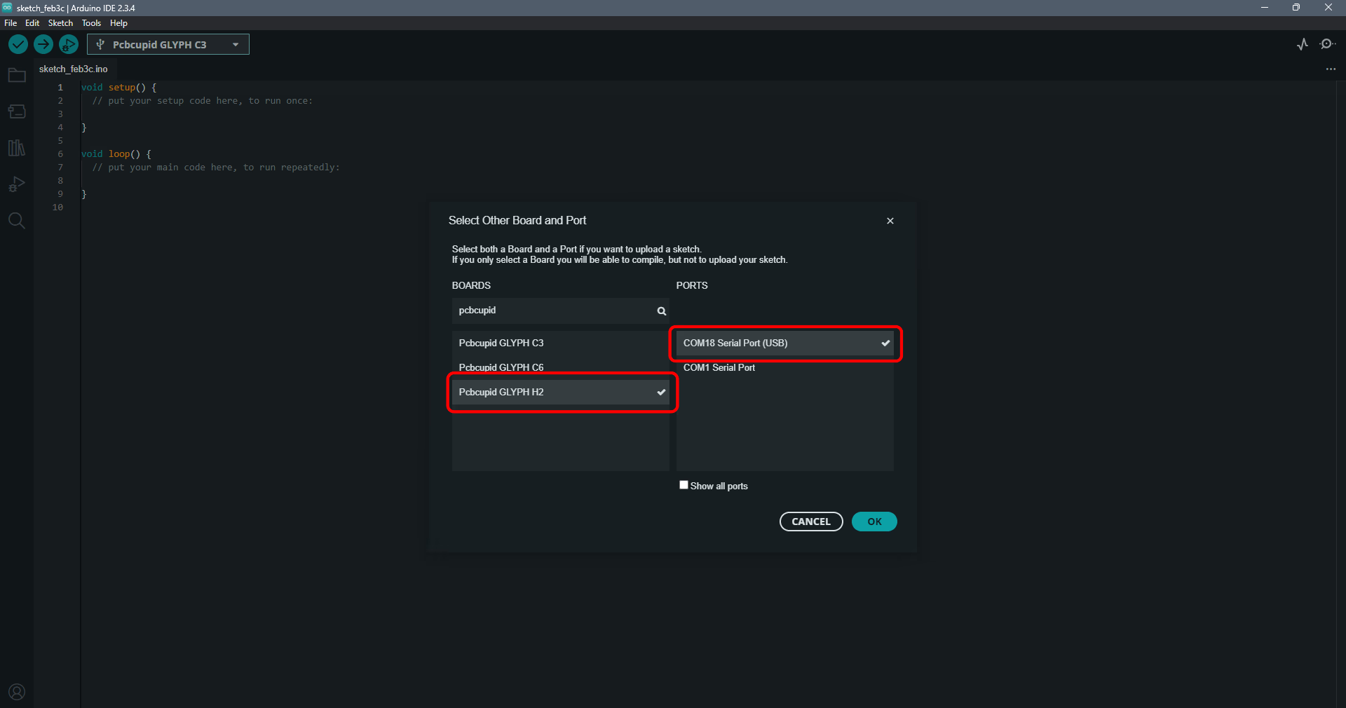
* Now go to **select other board and port > Pcbcupid Glyph C6 > Select your COM port.**
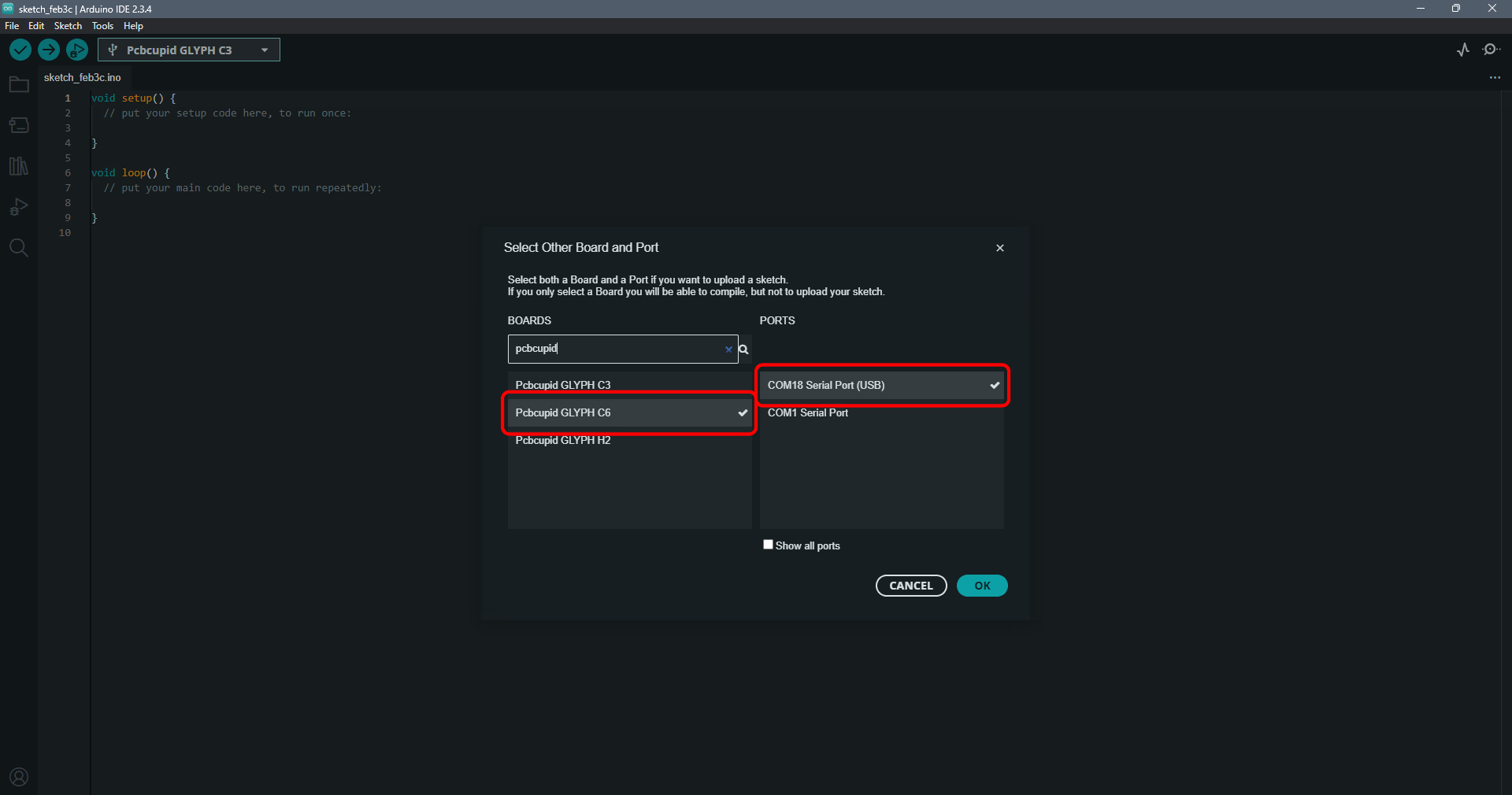
Now you can use the code below for the co-ordinator to act as a switch:
```cpp theme={null}
#ifndef ZIGBEE_MODE_ZCZR
#error "Zigbee coordinator mode is not selected in Tools->Zigbee mode"
#endif
#include "Zigbee.h"
/* Zigbee switch configuration */
#define SWITCH_ENDPOINT_NUMBER 5
#define GPIO_INPUT_IO_TOGGLE_SWITCH 9
#define PAIR_SIZE(TYPE_STR_PAIR) (sizeof(TYPE_STR_PAIR) / sizeof(TYPE_STR_PAIR[0]))
typedef enum {
SWITCH_ON_CONTROL,
SWITCH_OFF_CONTROL,
SWITCH_ONOFF_TOGGLE_CONTROL,
SWITCH_LEVEL_UP_CONTROL,
SWITCH_LEVEL_DOWN_CONTROL,
SWITCH_LEVEL_CYCLE_CONTROL,
SWITCH_COLOR_CONTROL,
} SwitchFunction;
typedef struct {
uint8_t pin;
SwitchFunction func;
} SwitchData;
typedef enum {
SWITCH_IDLE,
SWITCH_PRESS_ARMED,
SWITCH_PRESS_DETECTED,
SWITCH_PRESSED,
SWITCH_RELEASE_DETECTED,
} SwitchState;
static SwitchData buttonFunctionPair[] = {{GPIO_INPUT_IO_TOGGLE_SWITCH, SWITCH_ONOFF_TOGGLE_CONTROL}};
ZigbeeSwitch zbSwitch = ZigbeeSwitch(SWITCH_ENDPOINT_NUMBER);
/********************* Zigbee functions **************************/
static void onZbButton(SwitchData *button_func_pair) {
if (button_func_pair->func == SWITCH_ONOFF_TOGGLE_CONTROL) {
// Send toggle command to the light
Serial.println("Toggling light");
zbSwitch.lightToggle();
}
}
/********************* GPIO functions **************************/
static QueueHandle_t gpio_evt_queue = NULL;
static void IRAM_ATTR onGpioInterrupt(void *arg) {
xQueueSendFromISR(gpio_evt_queue, (SwitchData *)arg, NULL);
}
static void enableGpioInterrupt(bool enabled) {
for (int i = 0; i < PAIR_SIZE(buttonFunctionPair); ++i) {
if (enabled) {
enableInterrupt((buttonFunctionPair[i]).pin);
} else {
disableInterrupt((buttonFunctionPair[i]).pin);
}
}
}
/********************* Arduino functions **************************/
void setup() {
Serial.begin(115200);
//Optional: set Zigbee device name and model
zbSwitch.setManufacturerAndModel("Espressif", "ZigbeeSwitch");
//Optional to allow multiple light to bind to the switch
zbSwitch.allowMultipleBinding(true);
//Add endpoint to Zigbee Core
Serial.println("Adding ZigbeeSwitch endpoint to Zigbee Core");
Zigbee.addEndpoint(&zbSwitch);
//Open network for 180 seconds after boot
Zigbee.setRebootOpenNetwork(180);
// Init button switch
for (int i = 0; i < PAIR_SIZE(buttonFunctionPair); i++) {
pinMode(buttonFunctionPair[i].pin, INPUT_PULLUP);
/* create a queue to handle gpio event from isr */
gpio_evt_queue = xQueueCreate(10, sizeof(SwitchData));
if (gpio_evt_queue == 0) {
Serial.println("Queue creating failed, rebooting...");
ESP.restart();
}
attachInterruptArg(buttonFunctionPair[i].pin, onGpioInterrupt, (void *)(buttonFunctionPair + i), FALLING);
}
// When all EPs are registered, start Zigbee with ZIGBEE_COORDINATOR mode
if (!Zigbee.begin(ZIGBEE_COORDINATOR)) {
Serial.println("Zigbee failed to start!");
Serial.println("Rebooting...");
ESP.restart();
}
Serial.println("Waiting for Light to bound to the switch");
//Wait for switch to bound to a light:
while (!zbSwitch.bound()) {
Serial.printf(".");
delay(500);
}
// Optional: List all bound devices and read manufacturer and model name
std::list boundLights = zbSwitch.getBoundDevices();
for (const auto &device : boundLights) {
Serial.printf("Device on endpoint %d, short address: 0x%x\r\n", device->endpoint, device->short_addr);
Serial.printf(
"IEEE Address: %02X:%02X:%02X:%02X:%02X:%02X:%02X:%02X\r\n", device->ieee_addr[7], device->ieee_addr[6], device->ieee_addr[5], device->ieee_addr[4],
device->ieee_addr[3], device->ieee_addr[2], device->ieee_addr[1], device->ieee_addr[0]
);
char *manufacturer = zbSwitch.readManufacturer(device->endpoint, device->short_addr, device->ieee_addr);
char *model = zbSwitch.readModel(device->endpoint, device->short_addr, device->ieee_addr);
if (manufacturer != nullptr) {
Serial.printf("Light manufacturer: %s\r\n", manufacturer);
}
if (model != nullptr) {
Serial.printf("Light model: %s\r\n", model);
}
}
Serial.println();
}
void loop()
{
// Handle button switch in loop()
uint8_t pin = 0;
SwitchData buttonSwitch;
static SwitchState buttonState = SWITCH_IDLE;
bool eventFlag = false;
/* check if there is any queue received, if yes read out the buttonSwitch */
if (xQueueReceive(gpio_evt_queue, &buttonSwitch, portMAX_DELAY))
{
pin = buttonSwitch.pin;
enableGpioInterrupt(false);
eventFlag = true;
}
while (eventFlag)
{
bool value = digitalRead(pin);
switch (buttonState) {
case SWITCH_IDLE: buttonState = (value == LOW) ? SWITCH_PRESS_DETECTED : SWITCH_IDLE; break;
case SWITCH_PRESS_DETECTED: buttonState = (value == LOW) ? SWITCH_PRESS_DETECTED : SWITCH_RELEASE_DETECTED; break;
case SWITCH_RELEASE_DETECTED:
buttonState = SWITCH_IDLE;
/* callback to button_handler */
(*onZbButton)(&buttonSwitch);
break;
default: break;
}
if (buttonState == SWITCH_IDLE)
{
enableGpioInterrupt(true);
eventFlag = false;
break;
}
vTaskDelay(10 / portTICK_PERIOD_MS);
}
// print the bound lights every 10 seconds
static uint32_t lastPrint = 0;
if (millis() - lastPrint > 10000)
{
lastPrint = millis();
zbSwitch.printBoundDevices(Serial);
}
}
```
### Configure Co-Ordinator
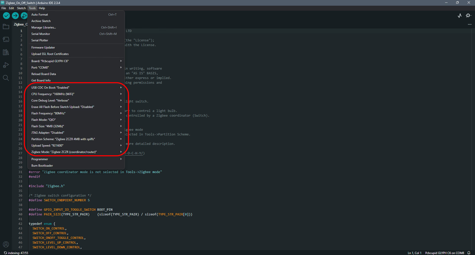
To configure the board, Go to Tools and set the following configuration keys in place.
1. Make sure the **USB CDC On Boot is “Enabled”**
2. Set the **Core Debug level to “Verbose”**
3. Set the **flash size** to **“4MB (32Mb)”**
4. Make sure that the **partition scheme** is set to: **“Zigbee ZCZR 4MB with spiffs”**
5. Set the **Zigbee mode: “Zigbee ZCZR (coordinator/router)”**
Why do we do these settings?
1. **Enable USB CDC on Boot**: Activates USB serial communication on startup for easier debugging and setup.
2. **Set Core Debug Level to Verbose**: Provides detailed log output to help troubleshoot issues during development.
3. **Set Flash Size to 4MB (32Mb)**: Ensures sufficient storage for firmware, Zigbee stack, and additional files.
4. **Set Partition Scheme to “Zigbee ZCZR 4MB with spiffs”**: Allocates memory for both Zigbee network functionality and SPIFFS file storage.
5. **Set Zigbee Mode to “Zigbee ZCZR (coordinator/router)”**: Configures the device as a coordinator/router for managing or extending a Zigbee network.
* Finally! compile, upload the code and start with programming the end-device.
## Step 3C: Setup the end-device.
The end-device is the one that receives the signal from the coordinator and completes the action initiated by the coordinator it responds to. Thus, a Zigbee network can occupy up to 240 devices practically. These end devices form a connection with the coordinator through the same network ID, making communication possible. The communication can be unicast, multicast or broadcast.
Plug in the GLYPH-H2 (GLYPH C6 can be used here as well) board. Here the GLYPH-H2 we'll act as a end- device, which on receiving the signal from co-ordinator glows it’s in-built LED.
* Now go to **select other board and port > Pcbcupid Glyph H2 > Select your COM port**.
### Configure end-device
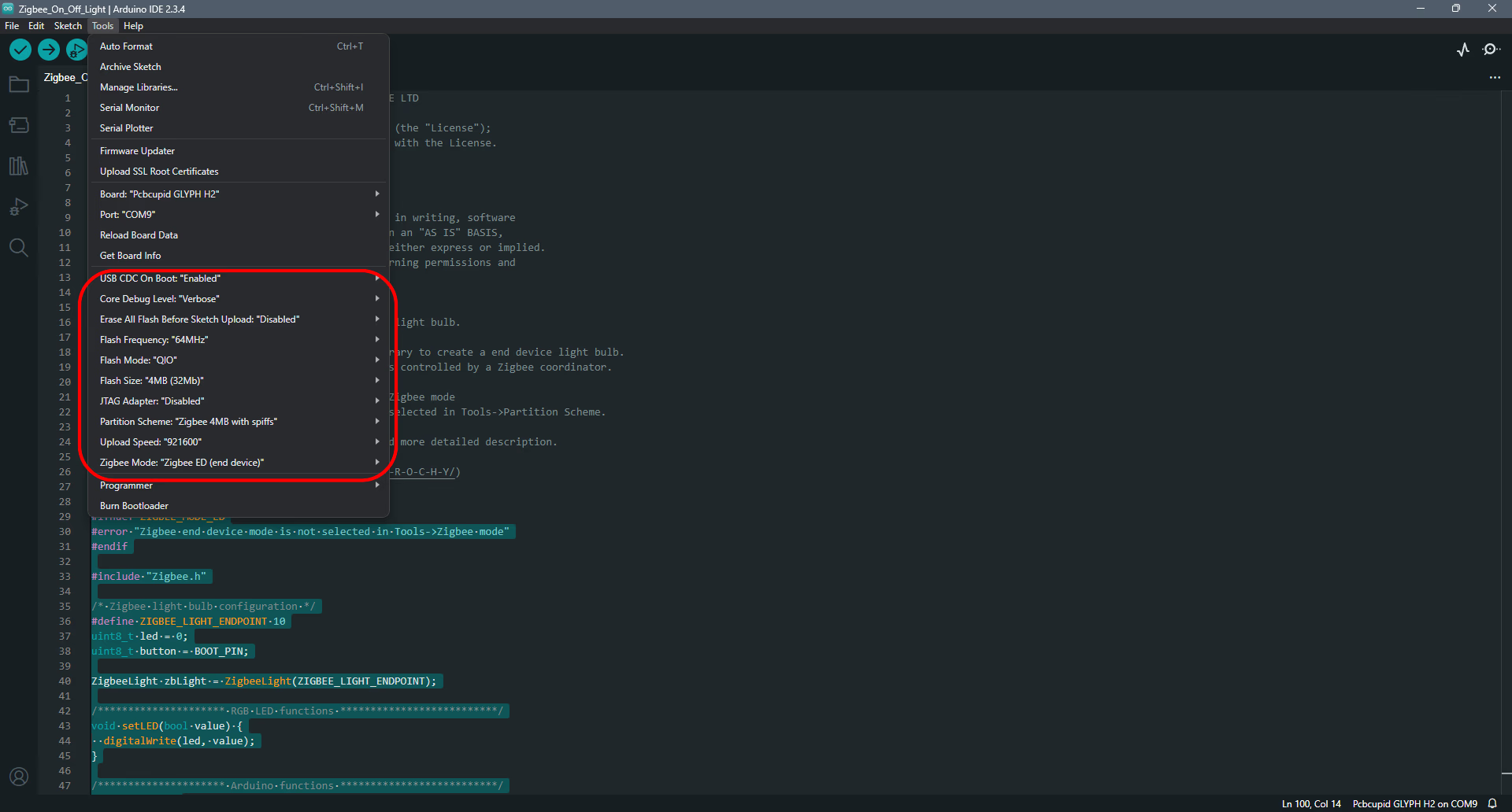
* To configure the board, Go to Tools and set the following configuration keys in place.
1. Make sure the **USB CDC** On Boot is **“Enabled”**
2. Set the Core Debug level to **“Verbose”**
3. Set the flash size to **“4MB (32Mb)”**
4. Make sure that the partition scheme is set to: **“Zigbee 4MB with spiffs”**
5. Set the Zigbee mode: **“Zigbee ED (End device)”**
Now you can use the code below for the end-device to act as a light (controlled device):
```cpp theme={null}
#ifndef ZIGBEE_MODE_ED
#error "Zigbee end device mode is not selected in Tools->Zigbee mode"
#endif
#include "Zigbee.h"
/* Zigbee light bulb configuration */
#define ZIGBEE_LIGHT_ENDPOINT 10
uint8_t led = 0;
uint8_t button = BOOT_PIN;
ZigbeeLight zbLight = ZigbeeLight(ZIGBEE_LIGHT_ENDPOINT);
/********************* RGB LED functions **************************/
void setLED(bool value) {
digitalWrite(led, value);
}
/********************* Arduino functions **************************/
void setup() {
Serial.begin(115200);
// Init LED and turn it OFF (if LED_PIN == RGB_BUILTIN, the rgbLedWrite() will be used under the hood)
pinMode(led, OUTPUT);
digitalWrite(led, LOW);
// Init button for factory reset
pinMode(button, INPUT_PULLUP);
//Optional: set Zigbee device name and model
zbLight.setManufacturerAndModel("Espressif", "ZBLightBulb");
// Set callback function for light change
zbLight.onLightChange(setLED);
//Add endpoint to Zigbee Core
Serial.println("Adding ZigbeeLight endpoint to Zigbee Core");
Zigbee.addEndpoint(&zbLight);
// When all EPs are registered, start Zigbee. By default acts as ZIGBEE_END_DEVICE
if (!Zigbee.begin()) {
Serial.println("Zigbee failed to start!");
Serial.println("Rebooting...");
ESP.restart();
}
Serial.println("Connecting to network");
while (!Zigbee.connected()) {
Serial.print(".");
delay(100);
}
Serial.println();
}
void loop()
{
// Checking button for factory reset
if (digitalRead(button) == LOW)
{ // Push button pressed
// Key debounce handling
delay(100);
int startTime = millis();
while (digitalRead(button) == LOW)
{
delay(50);
if ((millis() - startTime) > 3000)
{
// If key pressed for more than 3secs, factory reset Zigbee and reboot
Serial.println("Resetting Zigbee to factory and rebooting in 1s.");
delay(1000);
Zigbee.factoryReset();
}
}
// Toggle light by pressing the button
zbLight.setLight(!zbLight.getLightState());
}
delay(100);
}
```
-Compile and run the code and observe the serial monitor to get insights on how the code is working.
Some additional things to remember would be:
1. In the code “#define GPIO\_INPUT\_IO\_TOGGLE\_SWITCH 9” do not forget to add the GPIO pin that corresponds to the in-built LED/Button pin in GLYPH-H2/GLYPH-C6 or any other glyph board you connect.
2. Always set the partition scheme relevant to the device you want to set it as - coordinator or end device.
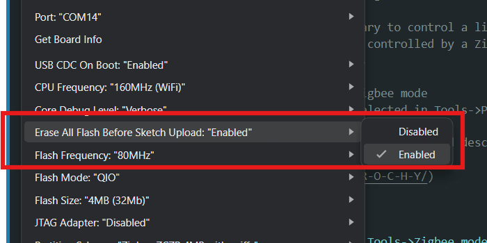
If the device keeps continuously resetting, go to Tools> Erase all flash before sketch upload> Enabled. This will erase all the memory from the current board and gives a window of 180 seconds to reconfigure a new board to join the Zigbee network.
 ## Step 4: Observe the Output on Serial Monitor
Open the serial monitor to observe the output along with the physical hardware:
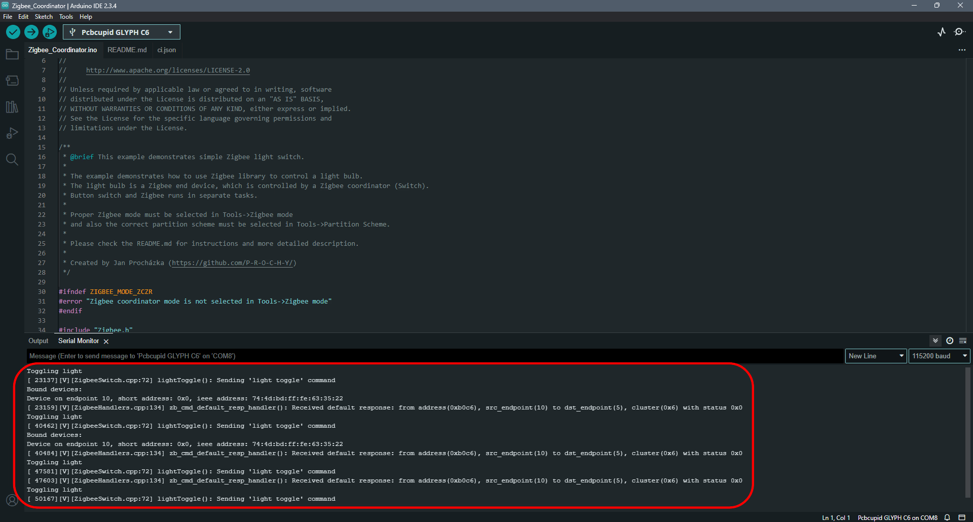
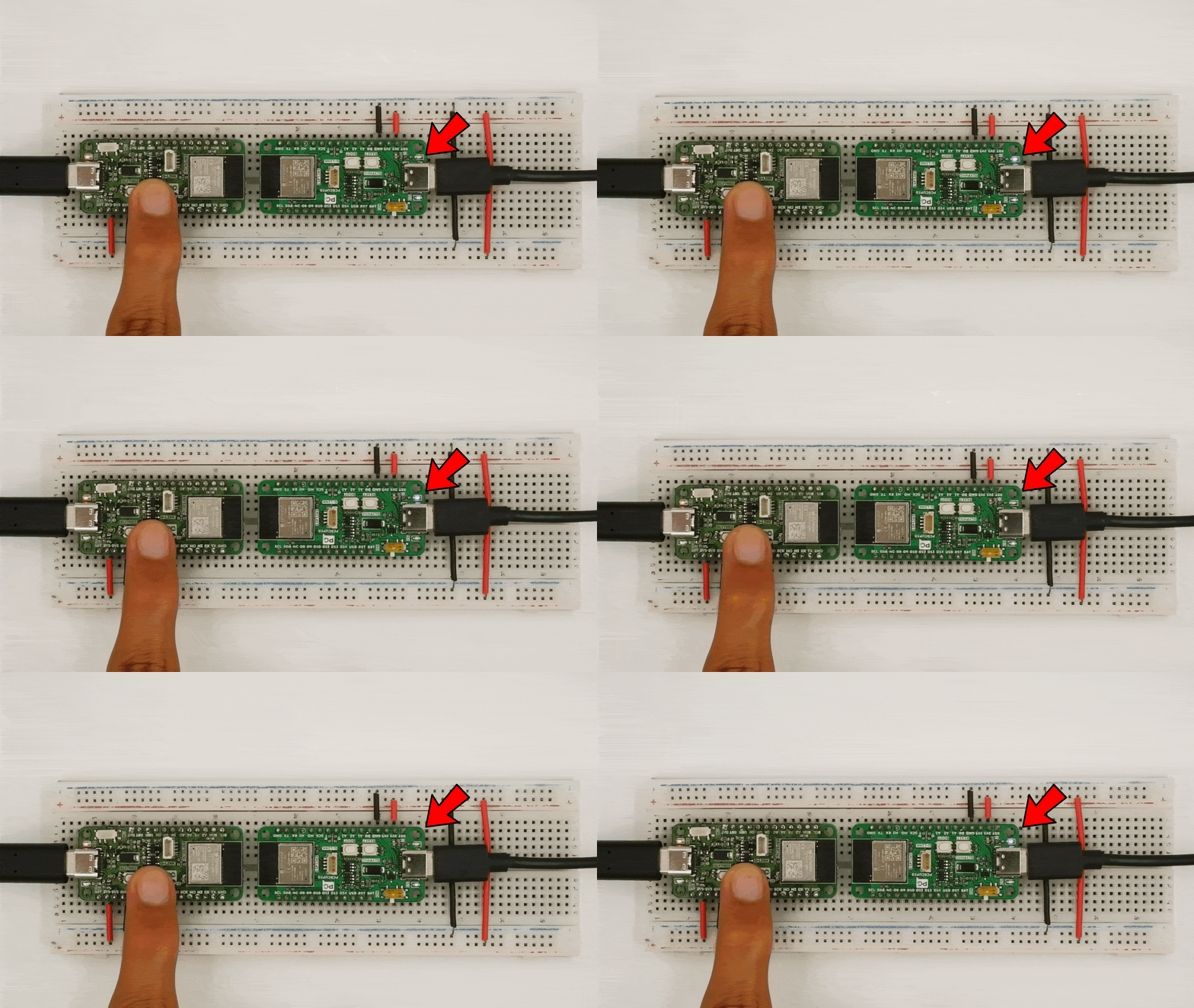
## Step 4: Observe the Output on Serial Monitor
Open the serial monitor to observe the output along with the physical hardware: