> ## Documentation Index
> Fetch the complete documentation index at: https://learn.pcbcupid.com/llms.txt
> Use this file to discover all available pages before exploring further.
> Control a 28BYJ-48 unipolar stepper motor using the ULN2003 driver module and a Glyph ESP32-C6 board with Arduino half-step and Stepper library code.
# Unipolar Stepper Motor (28BYJ-48)
# Unipolar Stepper Motor (28BYJ-48)
## Overview
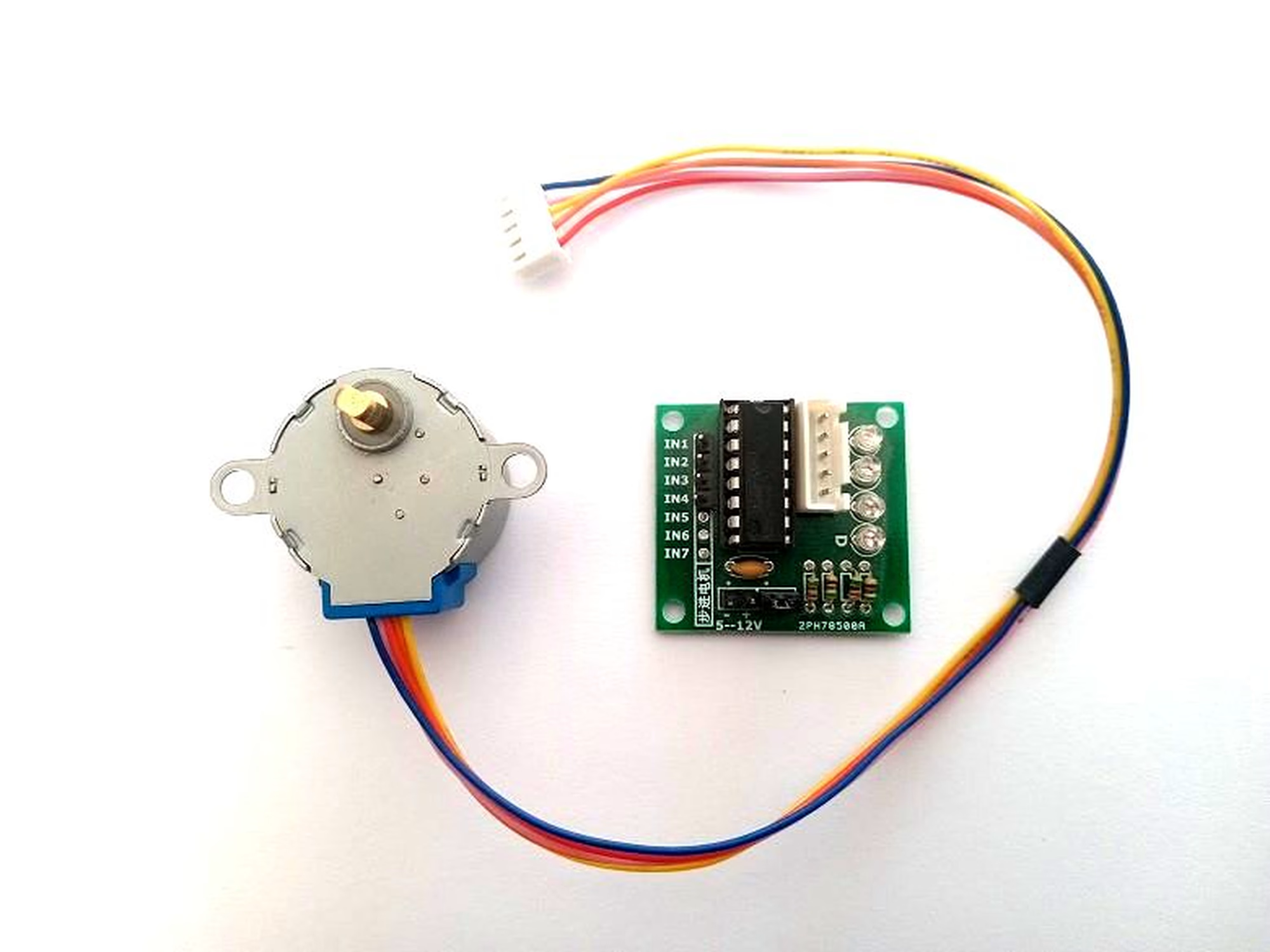
A stepper motor moves in discrete, precise steps instead of spinning freely like a DC motor. The **28BYJ-48** is a unipolar stepper: it has four coils with one common wire, which the **ULN2003 driver module** switches on and off in a fixed sequence. Each step of the sequence nudges the rotor forward by a tiny angle, so the shaft position is exactly predictable.
The 28BYJ-48 is rated for **5 V** and comes with a **64:1 reduction gearbox**, which trades almost all of its speed for torque and precision — the output shaft tops out around **20–25 RPM**:
* **2048 steps** per revolution in full-step mode
* **4096 steps** per revolution in half-step mode
* Half-step mode gives smaller, smoother steps (about 0.088° per step at the output shaft)
The motor draws roughly **100 mA per coil**. A GPIO pin can neither source that current nor survive the voltage spikes a coil produces when switched off, so the coils are always driven through the ULN2003 module — seven Darlington transistor pairs with built-in flyback diodes. Its inputs are driven directly by the GLYPH board's GPIO pins.
The motor is rotated by energising the coils one after another. The half-step sequence used in this tutorial is:
| Step | IN1 | IN2 | IN3 | IN4 |
| ---- | --- | --- | --- | --- |
| 1 | 1 | 1 | 0 | 0 |
| 2 | 0 | 1 | 0 | 0 |
| 3 | 0 | 1 | 1 | 0 |
| 4 | 0 | 0 | 1 | 0 |
| 5 | 0 | 0 | 1 | 1 |
| 6 | 0 | 0 | 0 | 1 |
| 7 | 1 | 0 | 0 | 1 |
| 8 | 1 | 0 | 0 | 0 |
Repeating this table forward rotates the shaft one way; repeating it backward rotates the other way. The speed is set by the delay between rows.
The rows energise **adjacent coils** in the motor's physical order — the 28BYJ-48's coils sit around the rotor in the order blue, pink, yellow, orange (IN1-IN2-IN3-IN4). A sequence that energises non-adjacent coils pulls the rotor forward, then back, so the shaft buzzes in place instead of turning. The same quirk is why the Stepper library in the alternative section below needs its pins passed as IN1-IN3-IN2-IN4.
## Pin Configuration
The ULN2003 module has four logic inputs (IN1–IN4), two power pins, and a 5-pin socket for the motor's JST plug.
| ULN2003 driver module | GLYPH-C6 |
| --------------------- | --------- |
| IN1 | GPIO 14 |
| IN2 | GPIO 15 |
| IN3 | GPIO 18 |
| IN4 | GPIO 19 |
| GND | GND |
| VCC | USB (5 V) |
The module's power terminals accept a 5–12 V supply — feed it **5 V**, since the 28BYJ-48 is a 5 V motor.
The 28BYJ-48's 5-wire JST plug (red is the common wire, carried to +5 V by the module) goes straight into the module's motor socket. Typical wire colours are IN1 = blue, IN2 = pink, IN3 = yellow, IN4 = orange, but many clones use different colours — if the motor vibrates instead of turning, swap the IN2 and IN3 wires.
## Key Features
* **28BYJ-48 unipolar stepper** — 4 coils + common, 5 V, about 100 mA per coil
* **64:1 reduction gearbox** — high torque (about 34 mN·m) and self-locking output shaft
* **2048 / 4096 steps per revolution** — full-step / half-step
* **ULN2003 driver module** — Darlington array with flyback diodes, accepts a 5–12 V supply
* **Direction and speed** fully software-controlled — no encoder needed for known distances
## Application
* Small robotics and camera pan-tilt mounts
* 3D printer extruder feeders
* Air-conditioner louvres and automated blinds
* Valve and actuator positioning
* Any project needing slow, precise, repeatable rotation
## Step 1: Hardware Required
1. [Pcbcupid GLYPH-C6](https://shop.pcbcupid.com/product/gd002/) board
2. 28BYJ-48 unipolar stepper motor
3. ULN2003 driver module
4. 6 × jumper wires (female–female)
5. USB-C cable for power and upload
## Step 2: Circuit Diagram

Wire the driver module to the GLYPH-C6 as listed in [Pin Configuration](#pin-configuration):
* IN1 → GPIO 14, IN2 → GPIO 15, IN3 → GPIO 18, IN4 → GPIO 19
* GND of the driver → GND of the board (grounds must be shared)
* The driver's power input (the + and − terminals, which accept 5–12 V) → the board's **USB** pin, which carries 5 V while the board is powered over USB-C
* Plug the motor's 5-pin JST connector into the module's socket
The two coils energised at once in half-step mode draw about 200 mA in total, which a USB port handles comfortably. If the motor feels weak or the board resets, power the driver from an external 5 V 1 A supply instead (module + → supply +5 V, and tie the supply ground to the board's GND).
## Step 3: Code Setup
Open the Arduino IDE and paste the sketch below into a new file. It rotates the shaft one full revolution in one direction, pauses, then one revolution back.
```cpp theme={null}
// 28BYJ-48 unipolar stepper + ULN2003 driver on Pcbcupid GLYPH-C6
// Rotates the shaft one full revolution each way, then repeats.
// ULN2003 inputs -> GLYPH-C6 GPIOs
#define IN1 14
#define IN2 15
#define IN3 18
#define IN4 19
const int motorPins[4] = {IN1, IN2, IN3, IN4};
// Half-step sequence. Columns = {IN1, IN2, IN3, IN4}
// 1 = coil energised, 0 = coil off. The rows energise adjacent
// coils in the motor's physical order so the shaft rotates smoothly.
const int halfStepSequence[8][4] = {
{1, 1, 0, 0}, // IN1 + IN2
{0, 1, 0, 0}, // IN2
{0, 1, 1, 0}, // IN2 + IN3
{0, 0, 1, 0}, // IN3
{0, 0, 1, 1}, // IN3 + IN4
{0, 0, 0, 1}, // IN4
{1, 0, 0, 1}, // IN4 + IN1
{1, 0, 0, 0} // IN1
};
// The 64:1 gearbox turns 4096 half-steps into 1 revolution.
const int stepsPerRevolution = 4096;
// Milliseconds per half-step. Lower = faster (try 1 to 5).
int stepDelay = 2;
int currentStep = 0;
void setup() {
for (int i = 0; i < 4; i++) {
pinMode(motorPins[i], OUTPUT);
digitalWrite(motorPins[i], LOW);
}
}
void setStep(int step) {
for (int i = 0; i < 4; i++) {
digitalWrite(motorPins[i], halfStepSequence[step][i]);
}
}
// Move one half-step. dir: +1 one way, -1 the other.
void stepMotor(int dir) {
currentStep = (currentStep + dir + 8) % 8;
setStep(currentStep);
delay(stepDelay);
}
void loop() {
// One full revolution in one direction
for (int i = 0; i < stepsPerRevolution; i++) {
stepMotor(1);
}
delay(1000);
// One full revolution in the opposite direction
for (int i = 0; i < stepsPerRevolution; i++) {
stepMotor(-1);
}
delay(1000);
}
```
How it works: `halfStepSequence` holds the 8 half-step states from the table above. `stepMotor()` walks through the rows forward or backward, and `stepDelay` sets how long each state is held — the smaller the delay, the faster the shaft spins.
## Step 4: Upload the Code
1. Connect the GLYPH-C6 to your computer with the USB-C cable.
2. In the Arduino IDE, go to **Tools → Board → esp32 → Pcbcupid GLYPH C6**.
The **Pcbcupid GLYPH C6** board entry only appears when the installed esp32 core version is **greater than or equal to 3.1.0**.
3. Set **Tools → USB CDC On Boot → Enabled**.
If USB CDC On Boot is disabled, no serial data shows up in the Serial Monitor.
4. Select the board's port under **Tools → Port**.
5. Click the upload arrow button (or press **Ctrl + U**) and wait for the upload to finish.
## Step 5: Observe the Output
Once the upload completes, the motor shaft starts turning immediately:
* It spins one full revolution in one direction, pauses for a second, then one full revolution back — and repeats.
* Put a small tape flag on the shaft to see the rotation more clearly.
* Open the Serial Monitor at **115200 baud** if you add `Serial.println()` calls to the sketch.

### Things to Try
* **Change the speed** — edit `stepDelay` to `1` for faster or `5` for slower motion, and re-upload.
* **Find the speed limit** — at `stepDelay` of `1` the shaft does about 15 RPM comfortably. Lower values need a smooth acceleration ramp or the rotor loses sync and buzzes — the gearbox tops out around 20–25 RPM. This motor is built for slow, precise motion, not speed.
* **Change the distance** — replace `stepsPerRevolution` in the loops with `2048` for half a revolution, or `1024` for a quarter.
* **Go full-step** — energise only rows 1, 3, 5 and 7 of the table (`{1,1,0,0}`, `{0,1,1,0}`, `{0,0,1,1}`, `{1,0,0,1}`) and use `2048` steps per revolution. More torque, but rougher motion.
### Troubleshooting
* The shaft **vibrates but does not turn** — the energising sequence does not match your motor's physical coil order. The 28BYJ-48's four coils sit in a fixed order around the rotor (blue, pink, yellow, orange on most units), and energising non-adjacent coils pushes the rotor forward, then back, so it buzzes in place. Swap the wires on IN2 and IN3 (or try other orders) until it turns smoothly.
* The motor **turns sluggishly or stalls** — make sure the driver is powered with 5 V, and try an external 5 V 1 A supply with a common ground.
* The revolution **stops a hair short of exactly one turn** — the gearbox ratio is actually about 63.7:1, not 64:1. Use 4076 half-steps for a near-exact revolution.
## Alternative: Using the Arduino Stepper Library
The built-in **Stepper** library drives the same sequence with less code — at the cost of hiding how the motor works, and with one gotcha: the pins must be passed in the order **IN1-IN3-IN2-IN4** (not IN1-IN2-IN3-IN4) to match the motor's internal coil order, and one revolution is **2048** steps.
```cpp theme={null}
// 28BYJ-48 + ULN2003 using the built-in Stepper library.
#include
// With this library, 2048 steps = 1 revolution of the output shaft.
const int stepsPerRevolution = 2048;
// IMPORTANT: pin order is IN1-IN3-IN2-IN4, matching the motor's
// internal coil order — IN1-IN2-IN3-IN4 will not rotate smoothly.
Stepper myStepper(stepsPerRevolution, 14, 18, 15, 19);
void setup() {
myStepper.setSpeed(10); // output RPM (max about 15)
}
void loop() {
myStepper.step(stepsPerRevolution); // one revolution
delay(1000);
myStepper.step(-stepsPerRevolution); // and back
delay(1000);
}
```
Note that the library uses `delay()` internally, so while the motor is stepping, your sketch cannot do anything else. The manual sequence from Step 3 is the better base when you need to read sensors or run other tasks while the motor moves.