> ## Documentation Index
> Fetch the complete documentation index at: https://learn.pcbcupid.com/llms.txt
> Use this file to discover all available pages before exploring further.
> Drive a bipolar stepper motor at variable speeds using the DRV8833 motor driver and a Glyph ESP32 board with example Arduino code and wiring.
# Stepper Motor
# Stepper Motor
## Overview
Stepper motors allow precise control of angular position, speed, and acceleration. The DRV8825 stepper driver module provides an easy interface to control bipolar stepper motors via simple digital signals (STEP and DIR).
Stepper Motor
A stepper motor is a type of electric motor that moves in precise, small steps instead of spinning continuously like a regular motor.
* Each step rotates the motor by a fixed angle (called step angle).
* You can control position, speed, and direction very accurately.
* No need for feedback sensors (in most basic systems).
How does it work:
A stepper motor has:
* Multiple electromagnets (coils) arranged around a central rotor.
* When you energize coils in a specific sequence, the magnetic field causes the rotor to move one "step" at a time.
DRV8825 Driver:
The DRV8825 is a microstepping driver for controlling bipolar stepper motors. It can handle up to 2.5A per coil (with proper cooling) and supports up to 1/32 microstepping, allowing smooth and quiet motor operation.
Key Signals:
* STEP: Each pulse advances motor by one microstep.
* DIR: Sets direction of rotation (HIGH = one direction, LOW = opposite).
* ENABLE: Enables or disables motor coils (LOW = enable, HIGH = disable).
* Microstep Pins (MS1, MS2, MS3): Select microstepping resolution.
* VMOT & GND: Power supply for the motor.
## Pin Configuration
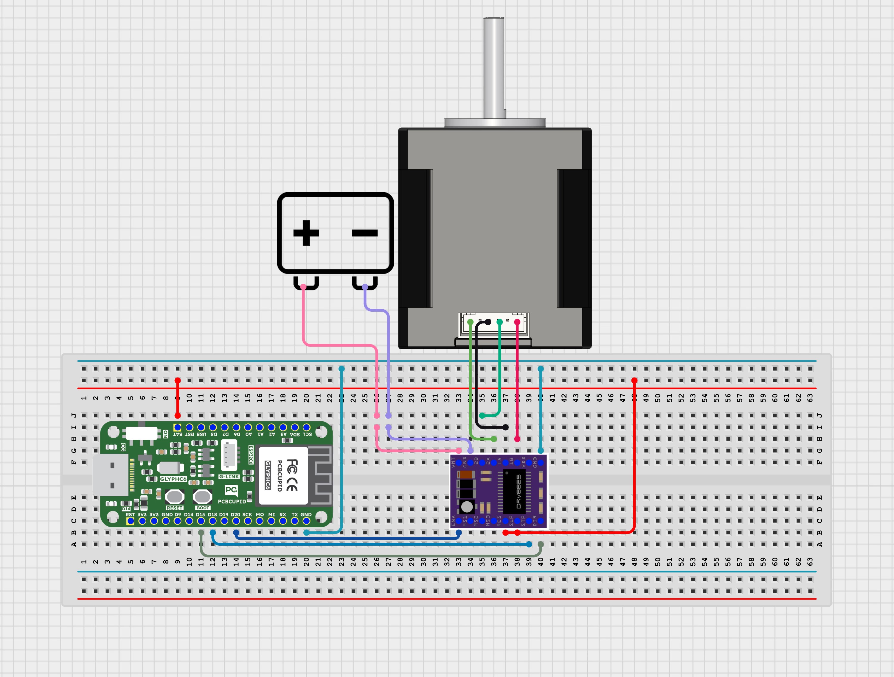
* STEP: GPIO 18
* DIR : GPIO 15
* ENABLE : GPIO 20 (OPTIONAL)
* VMOT: External Motor Power
* GND : External Motor Power
* GND (Logic) : GND (GLYPH BOARD)
* SLP : 5V SUPPLY (GLYPH BOARD)
* RST : 5V SUPPLY(GLYPH BOARD)
connect SLP and RST together, then tie to 5v supply in GLYPH BOARD :
* Common approach in DRV8825 modules.
* Keeps both active together.
## Key Features
* Accurate Stepper Motor Control
* Adjustable Speed via DelayMicroseconds
* Direction Control
* Enable/Disable Motor Driver
* Compatible with GLYPH-C6 (ESP32-C6)
## Application
* Precision motion control systems
* Positioning and alignment mechanisms
* Robotics and automation projects
* CNC machines and engraving systems
* 3D printers and fabrication devices
* Smart home motorized appliances
Conveyor and material handling systems
Camera sliders and pan-tilt systems
Automatic feeders and dispensing units
Valve and actuator control systems
Industrial control applications
IoT-based remote motor control projects
## Step 1: Hardware Required
1. GLYPH-C6 Board (ESP32-C6)
2. DRV8825 Stepper Motor Driver Module
3. Bipolar Stepper Motor (e.g., NEMA 17)
4. External Motor Power Supply (12V recommended)
## Step 2: Circuit Diagram
## Step 3: Code Setup
1. **Open Arduino IDE.**
2. **Make sure to install the library**
3. **Copy and paste the following code into the Arduino IDE:**
```cpp theme={null}
// For GLYPH-C6
// Define GPIO pins
#define STEP_PIN 18
#define DIR_PIN 15
#define ENABLE_PIN 20 // Optional (LOW = enabled)
// Define number of steps per revolution (depends on microstepping)
const int stepsPerRevolution = 19200; // Example for high microstepping
void setup() {
pinMode(STEP_PIN, OUTPUT);
pinMode(DIR_PIN, OUTPUT);
pinMode(ENABLE_PIN, OUTPUT);
digitalWrite(ENABLE_PIN, LOW); // Enable driver
Serial.begin(115200);
Serial.println("Starting Stepper Test...");
}
void loop() {
Serial.println("Rotating Clockwise...");
rotateStepper(true, stepsPerRevolution);
delay(1000);
Serial.println("Rotating Counter-Clockwise...");
rotateStepper(false, stepsPerRevolution);
delay(1000);
}
void rotateStepper(bool dir, int steps) {
digitalWrite(DIR_PIN, dir ? HIGH : LOW);
for (int i = 0; i < steps; i++) {
digitalWrite(STEP_PIN, HIGH);
delayMicroseconds(500); // Pulse HIGH
digitalWrite(STEP_PIN, LOW);
delayMicroseconds(1000); // Pulse LOW (adjust speed here)
}
}
```
## Step 4: Upload the Code
1. **Connect the Board**
* Connect your GLYPH board to your computer
2. **Select the Board and Port**
Do the following settings in your Arduino IDE,
* `Tools > Board > esp32 > Pcbcupid GLYPH C6`
For the `Pcbcupid Glyph C3 ` to appear under `Tools > Board > esp32`, the esp32 board version installed in the Arduino IDE should be greater or equal to 3.1.0.
* `Tools > Port` and select the port connected to your GLYPH.
* `Tools > USB CDC on Boot >` ***Enabled***
If `USB CDC on BOOT` not enabled, you won't be seeing any serial data on Arduino IDE.
3. **Upload the Code**
* Click the upload button (➡️ icon) or use the shortcut `CRTL + U` in Arduino IDE to upload the code to the board.
## Step 5: Observe the Output
* The stepper motor rotates clockwise and counterclockwise.
* Serial Monitor will display rotation direction and steps.
* Adjust delayMicroseconds() for speed tuning.
* Modify stepsPerRevolution to match your motor & microstepping settings.