> ## Documentation Index
> Fetch the complete documentation index at: https://learn.pcbcupid.com/llms.txt
> Use this file to discover all available pages before exploring further.
> Read direction, position, and button presses from a rotary encoder on the Glyph ESP32-C6 board using interrupts and example Arduino code.
# Rotary Encoder with Glyph ESP32-C6
# Rotary Encoder with Push Button on GLYPH Boards
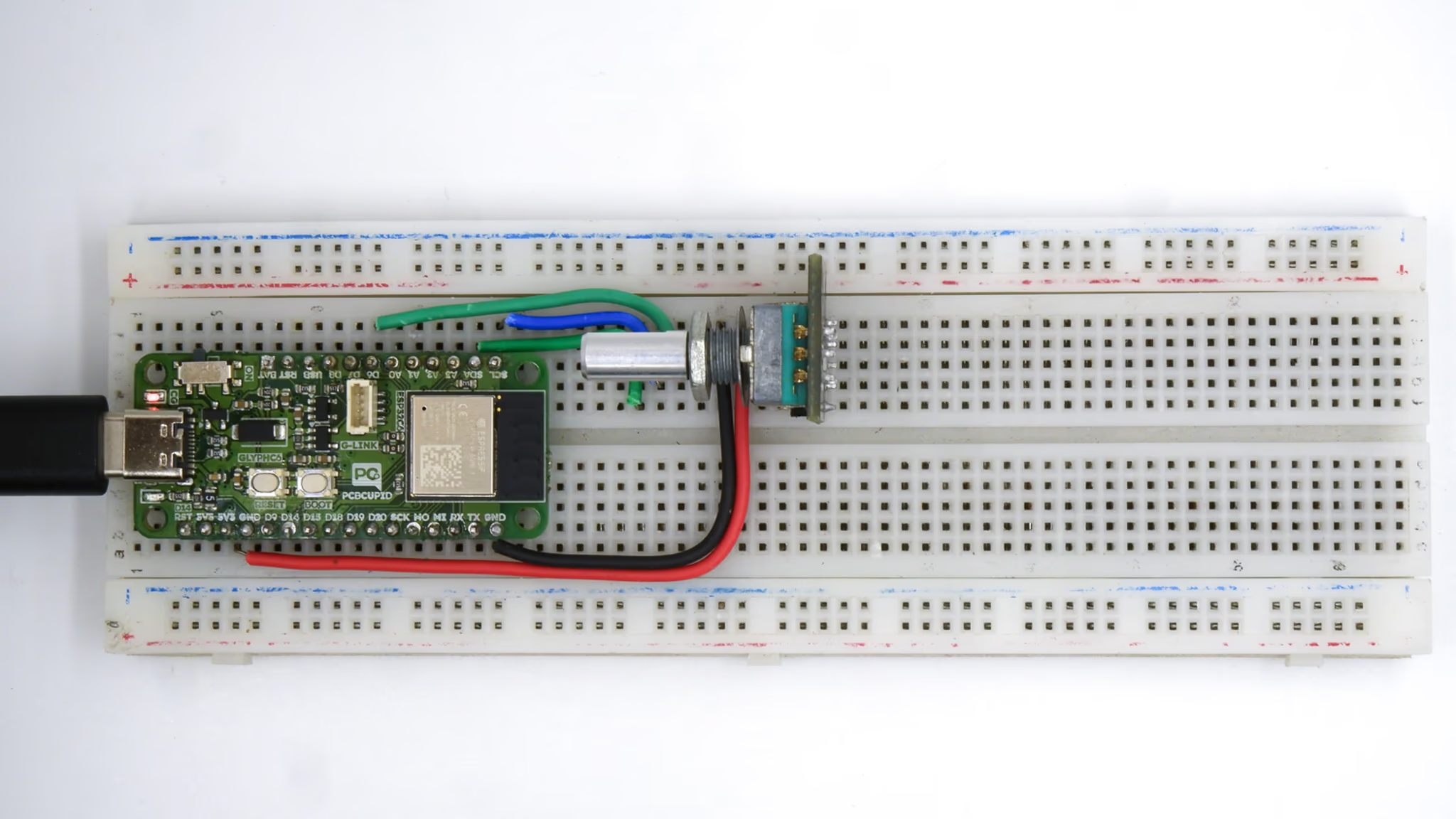
A rotary encoder is a mechanical device that converts rotational movement into digital signals. The encoder outputs two signals, typically labeled CLK (Clock) and DT (Data), which provide information about the direction and amount of rotation
A rotary encoder is a device that converts rotational motion into electrical signals. It is commonly used for position sensing, volume control, and menu navigation in electronics.
Inside a mechanical rotary encoder, the movement of the shaft generates electrical signals based on physical contact with a conductive disk. Let's break it down step by step.
Rotary Shaft: The part you rotate.
Slotted or Conductive Disk: A circular disk with evenly spaced openings or conductive areas.
Two Contact Brushes (A & B Terminals): These touch the disk to detect movement.
Spring Mechanism: Provides the "clicky" feel and holds the shaft in place.
Push Button Mechanism: (Optional) Detects when the knob is pressed.

This guide demonstrates how to use a rotary encoder with a push-button switch to track the position and direction of rotation, and detect button presses with a GLYPH board. This example is also compatible with [GLYPH-C3](https://shop.pcbcupid.com/product/gd001/) and [GLYPH-H2](https://shop.pcbcupid.com/product/gd003/) boards
The push-button switch on the encoder can be used to trigger specific actions when pressed.
## Step 1: Hardware Required
1. GLYPH-C6
2. Rotor encoder module
3. Jumper Wires
4. Breadboard
## Step 2: Circuit Diagram
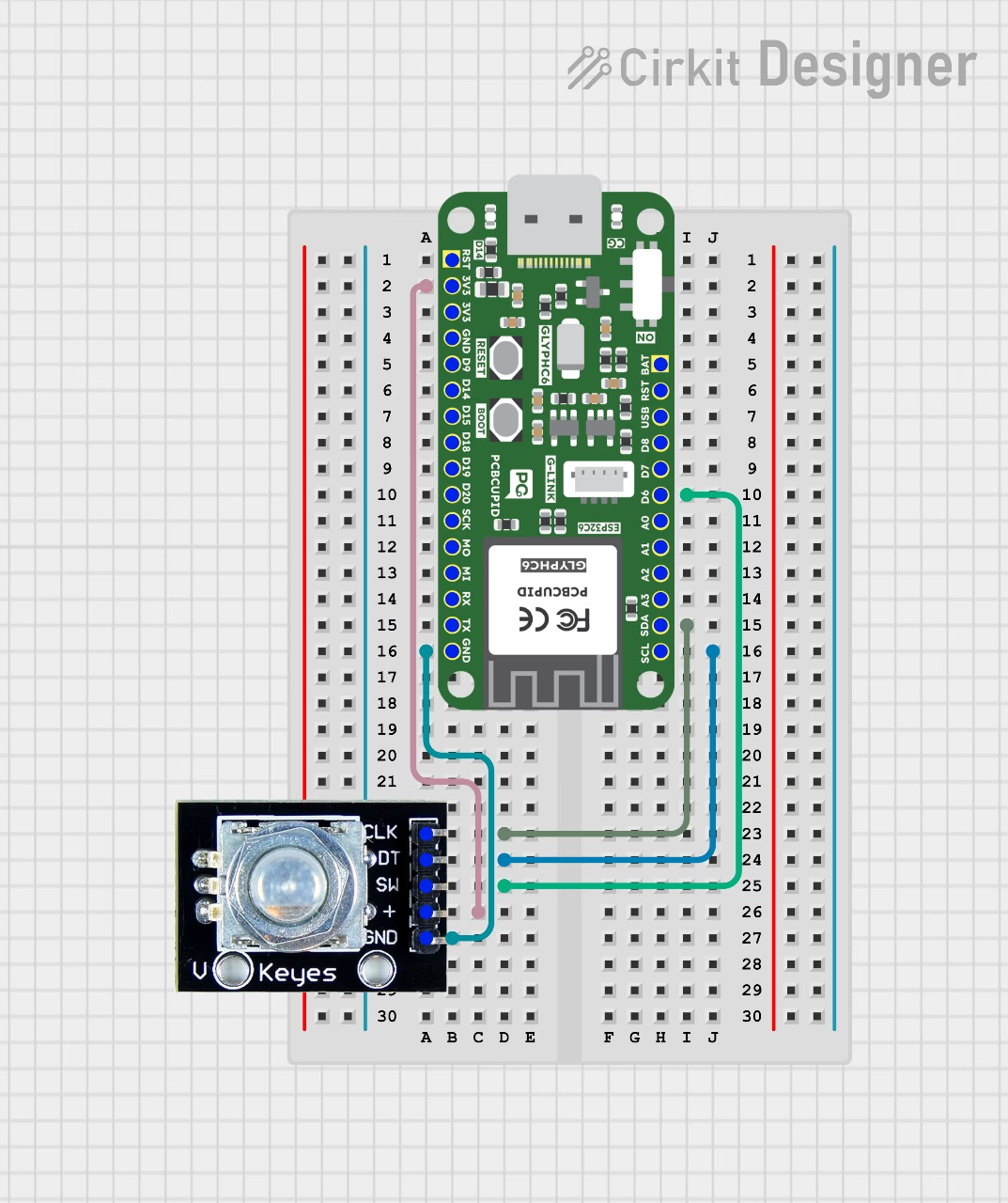
Rotary Encoder Pinout:
CLK (Clock): The main pin that outputs the clock signal used for determining rotation direction.
DT (Data): The data pin that works with the clock signal to calculate the rotation direction.
SW (Switch): The button pin used for detecting button presses.
Connect the encoder as follows:
CLK Pin → GPIO4 (or any available digital pin)
DT Pin → GPIO5 (or any available digital pin)
SW Pin → GPIO6 (or any available digital pin)
VCC → 3.3V or 5V (depending on your encoder module)
GND → Ground
## Step 3: Code Setup
```cpp theme={null}
#define ENCODER_CLK 4
#define ENCODER_DT 5
#define ENCODER_SW 6 // Button Pin
volatile int position = 0;
volatile int direction = 0;
bool buttonPressed = false;
void IRAM_ATTR readEncoder() {
if (digitalRead(ENCODER_CLK) == digitalRead(ENCODER_DT))
{
position--; // Counter-clockwise
direction = -1;
} else
{
position++; // Clockwise
direction = 1;
}
}
void IRAM_ATTR buttonISR() {
buttonPressed = true; // Set flag when button is pressed
}
void setup() {
Serial.begin(115200);
pinMode(ENCODER_CLK, INPUT_PULLUP);
pinMode(ENCODER_DT, INPUT_PULLUP);
pinMode(ENCODER_SW, INPUT_PULLUP);
attachInterrupt(digitalPinToInterrupt(ENCODER_CLK), readEncoder, CHANGE);
attachInterrupt(digitalPinToInterrupt(ENCODER_SW), buttonISR, FALLING);
}
void loop() {
static int lastPosition = 0;
// Print position update
if (lastPosition != position) {
Serial.print("Position: ");
Serial.print(position);
Serial.print(" | Direction: ");
Serial.println(direction == 1 ? "Increasing" : "Decreasing");
lastPosition = position;
}
// Print button press message
if (buttonPressed) {
Serial.println("Button Pressed!");
buttonPressed = false; // Reset flag
}
}
```
## Step 4: Upload the Code
1. **Connect the Board**
* Connect your GLYPH board to your computer
2. **Select the Board and Port**
Do the following settings in your Arduino IDE,
Do the following settings in your Arduino IDE,
* `Tools > Board > esp32 > Pcbcupid GLYPH C6`
For the `Pcbcupid GLYPH C6 ` to appear under `Tools > Board > esp32`, the esp32 board version installed in the Arduino IDE should be greater than or equal to 3.1.0.
* `Tools > Port` and select the port connected to your GLYPH.
* `Tools > USB CDC on Boot >` ***Enabled***
If `USB CDC on BOOT` not enabled, you won't be seeing any serial data on Arduino IDE.
3. **Upload the Code**
* Click the upload button (➡️ icon) or use the shortcut `CTRL + U` in Arduino IDE to upload the code to the board.
## Step 5: Observe the Output
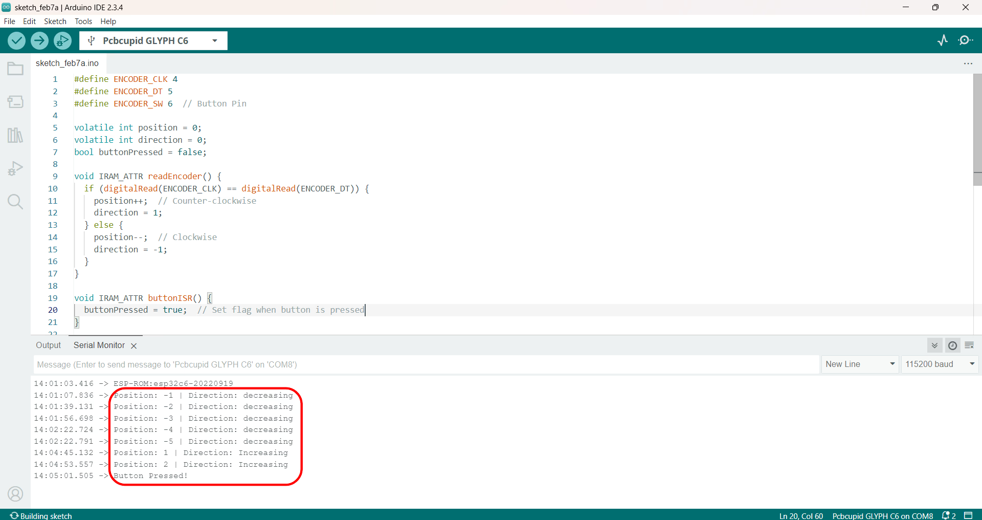
The Serial Monitor will display updates to the encoder's position and direction as it rotates. When the button is pressed, the message "Button Pressed!" will be printed to indicate that the button was activated.