> ## Documentation Index
> Fetch the complete documentation index at: https://learn.pcbcupid.com/llms.txt
> Use this file to discover all available pages before exploring further.
> Wire a 16x2 parallel LCD to a Glyph ESP32 board and print text using the LiquidCrystal library, covering pin connections and example code.
# Parallel LCD Display
# LCD
## Introduction
A 16×2 LCD is a character-based display capable of showing 16 characters per line on 2 lines, widely used in microcontroller projects for displaying text, numbers, or simple symbols.
When connected directly to a microcontroller, the LCD uses parallel communication, requiring multiple GPIO pins for control and data transfer.
## Pin Configuration
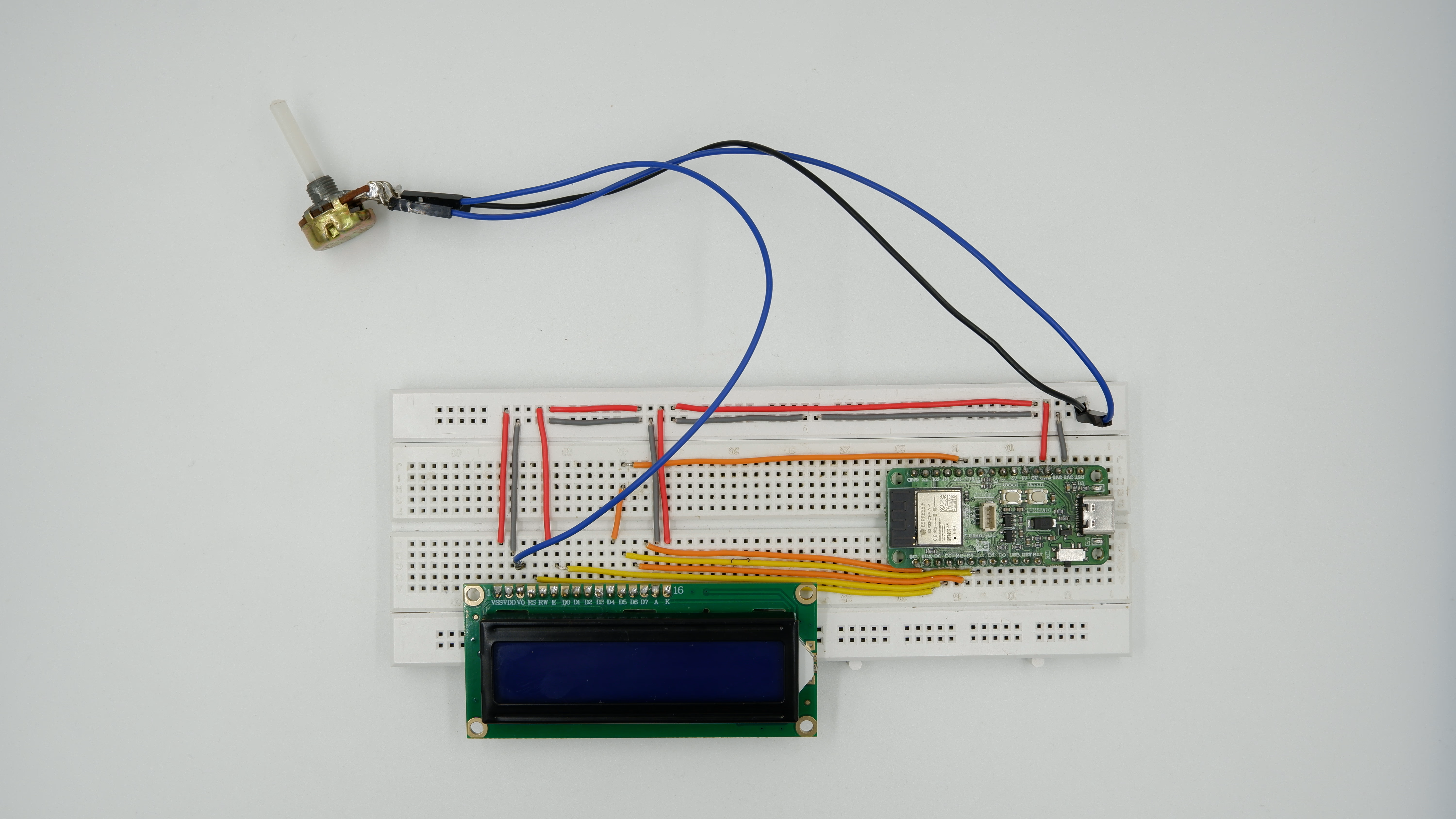
| LCD Pin | Function | Glyph-C3 |
| ------- | --------------- | ------------------- |
| RS | Register Select | GPIO 8 |
| RW | GND | GND |
| EN | Enable | GPIO 9 |
| D4 | Data 4 | GPIO 10 |
| D5 | Data 5 | GPIO 2 |
| D6 | Data 6 | GPIO 3 |
| D7 | Data 7 | GPIO 4 |
| VCC | Power | 5V |
| VSS | GROUND | GND |
| V0 | Contrast | Potentiometer wiper |
| LED+ | Backlight + | 5V |
| LED- | Backlight - | GND |
## Features
* Character Display: 16 columns × 2 rows.
* Controller: HD44780 or compatible.
* Parallel Communication: Direct pin-to-pin interface.
* Backlight: Built-in LED for better visibility.
* Custom Characters: Supports user-defined symbols via CGRAM.
* Contrast Control: Adjustable using a potentiometer.
* Voltage: Typically operates at 5V (some modules support 3.3V).
* Low Cost & Widely Available: Easy integration for embedded projects.
## Typical Applications
* Embedded system displays – show status or messages.
* Sensor data monitoring – temperature, voltage, humidity.
* Industrial control panels – parameter display.
* IoT projects – display device or network status.
* Educational and prototyping projects – learn microcontroller interfacing.
* Home automation devices – show time, modes, or device status.
* DIY electronics – simple, low-cost display solution.
## Step 1: Hardware Required
1. GLYPH
2. LCD Display
3. Potentiometer
## Step 2: Circuit Diagram
## Step 3: Code Setup
1. Open Arduino IDE.
2. Make sure to install the library
3. Copy and paste the following code into the Arduino IDE
```cpp theme={null}
#include //https://www.arduinolibraries.info/libraries/liquid-crystal-i2-c
// Initialize LCD with pin configuration: RS, EN, D4, D5, D6, D7
LiquidCrystal lcd(8, 9, 10, 2, 3, 4);
void setup() {
// Initialize LCD with 16 columns and 2 rows
lcd.begin(16, 2);
// Print to LCD
lcd.print("Hello ESP32!");
lcd.setCursor(0, 1);
lcd.print("LiquidCrystal");
}
void loop() {
// Static display - nothing needed
delay(1000);
}
```
## Step 4: Upload the Code
1. **Connect the Board**
* Connect your GLYPH board to your computer
2. **Select the Board and Port**
Do the following settings in your Arduino IDE,
* `Tools > Board > esp32 > Pcbcupid Glyph S3`
For the `Pcbcupid Glyph S3 ` to appear under `Tools > Board > esp32`, the esp32 board version installed in the Arduino IDE should be greater or equal to 3.1.0.
* `Tools > Port` and select the port connected to your GLYPH.
* `Tools > USB CDC on Boot >` ***Enabled***
If `USB CDC on BOOT` not enabled, you won't be seeing any serial data on Arduino IDE.
3. **Upload the Code**
* Click the upload button (➡️ icon) or use the shortcut `CRTL + U` in Arduino IDE to upload the code to the board.
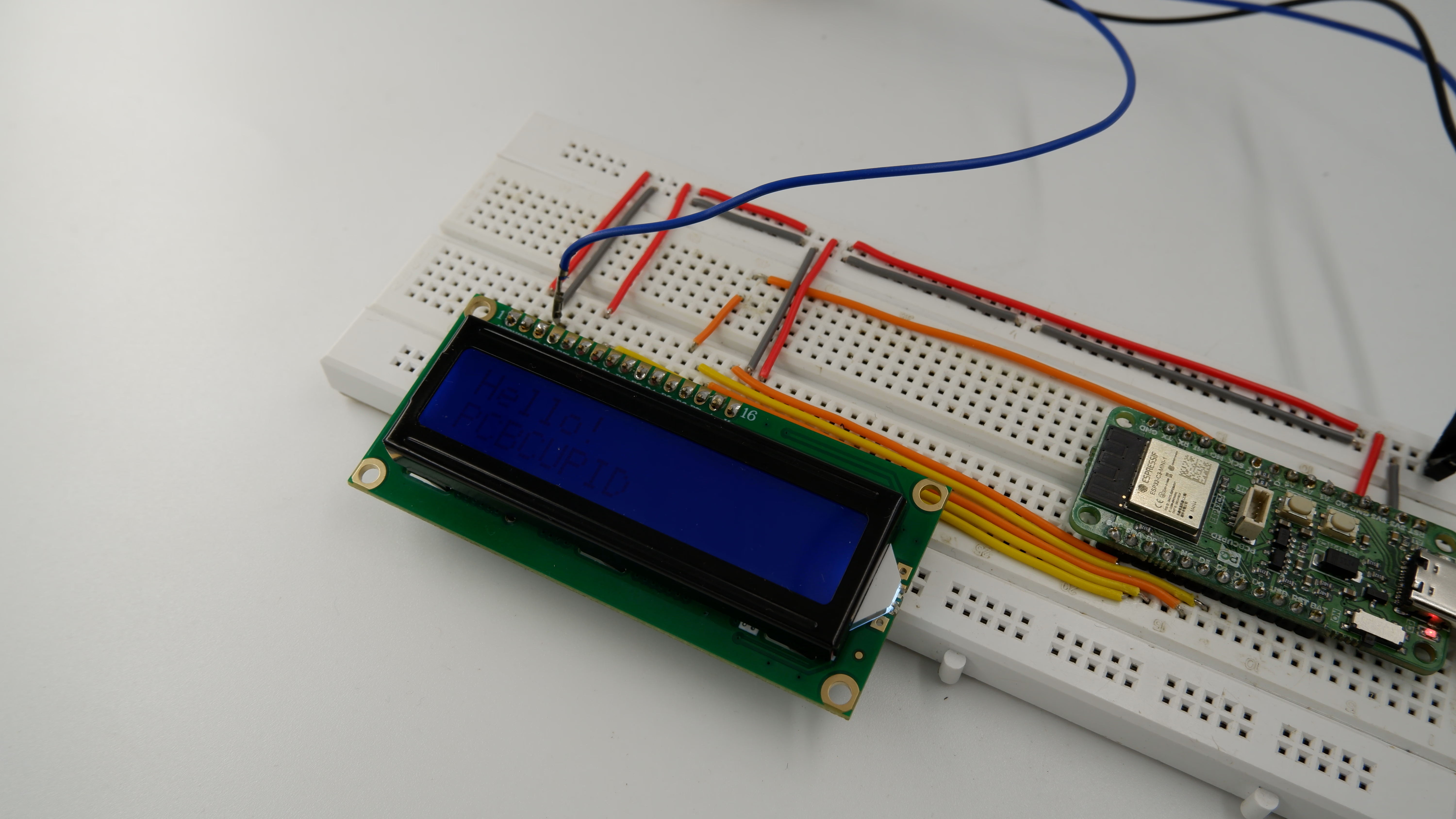
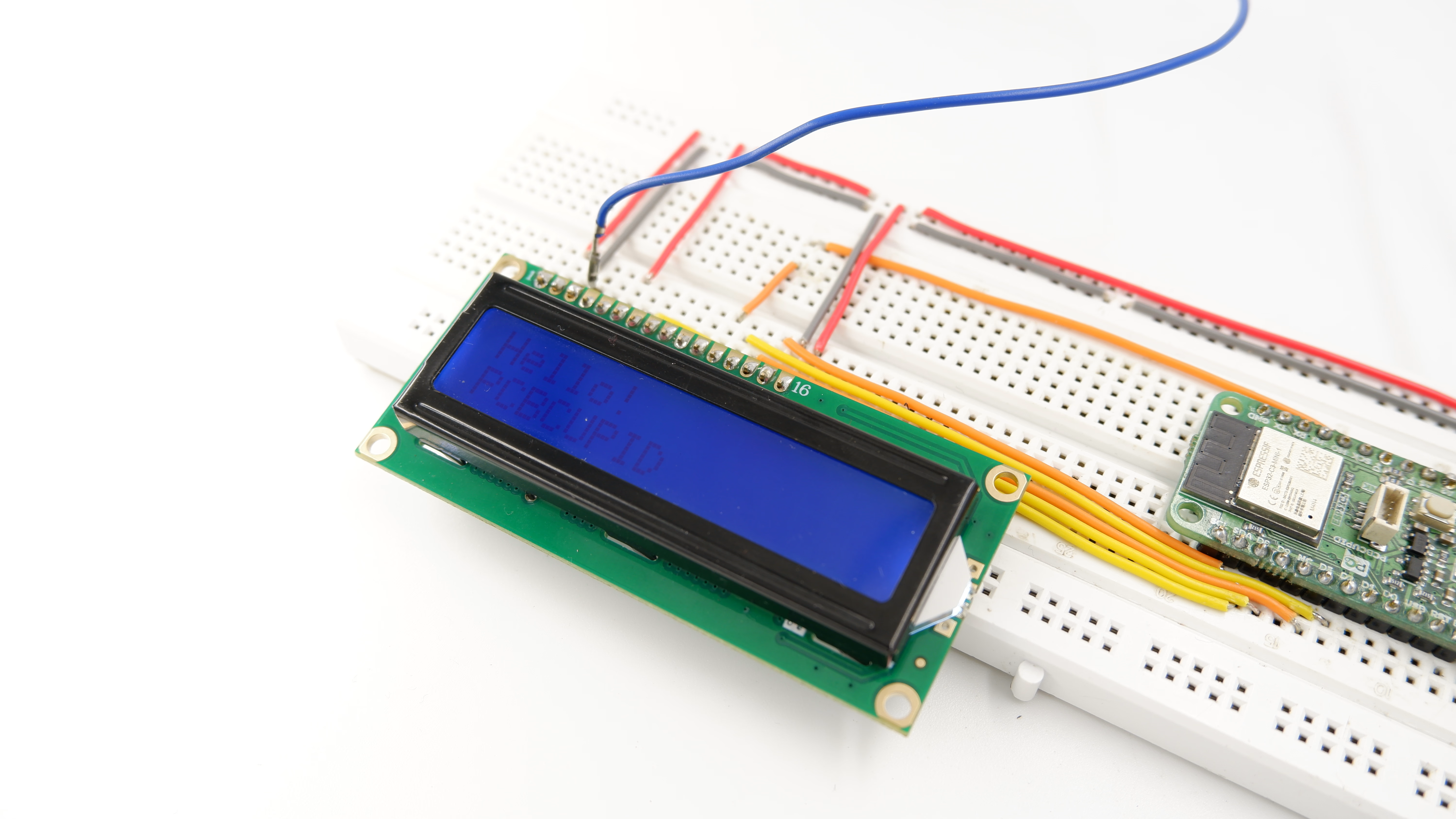
## Step 5: Observe Output on Serial Monitor
_result.jpg)