> ## Documentation Index
> Fetch the complete documentation index at: https://learn.pcbcupid.com/llms.txt
> Use this file to discover all available pages before exploring further.
> Interface the TTP223 capacitive touch sensor with the Glyph ESP32-C6 board to toggle onboard and external LEDs with debounce and edge detection.
# Touch Sensor (TTP223)
# Touch Sensor (TTP223)
## Overview
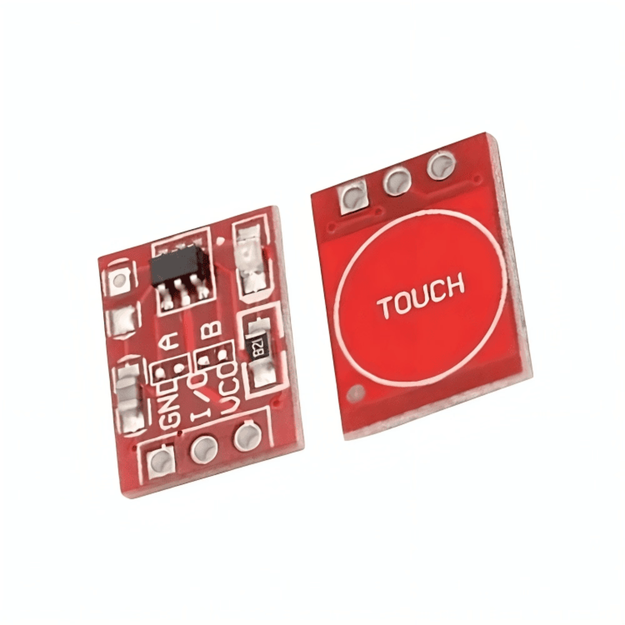
The **TTP223** is a capacitive touch sensor module: touch the metal pad on the module and its output pin goes HIGH; release it and the pin goes back LOW. The pad detects your finger through the change in capacitance, so there are no mechanical parts to wear out — you can even hide the pad behind a thin sheet of glass or acrylic.
The module is simple to use:
* **VCC** — accepts 2 V to 5.5 V, so the board's 3.3 V pin powers it directly
* **GND** — shared ground with the board
* **OUT** — digital output, HIGH while touched (momentary mode)
A small LED on the module itself lights up while the pad is touched. In this tutorial the sensor also toggles the **GLYPH-C6's onboard LED (GPIO 14)** and reports every touch and release over Serial, with debouncing so a single tap is never counted twice.
## Pin Configuration
| TTP223 module | GLYPH-C6 |
| ------------- | -------- |
| VCC | 3V |
| GND | GND |
| OUT | GPIO 20 |
The TTP223 works from 2 V to 5.5 V, so the board's 3.3 V rail is exactly right for it.
Some modules have an **A/B jumper** or solder pads that select the output mode: **A = momentary** (output HIGH only while touched — the default) and **B = toggle** (every touch flips the output and keeps it). This tutorial uses mode **A**, so make sure the jumper is on A if your module has one.
## Key Features
* **TTP223 capacitive sensing** — no moving parts, nothing to wear out
* **2.0–5.5 V supply** — runs directly from the GLYPH board's 3.3 V pin, sips under 60 µA
* **Digital output** — HIGH while touched (momentary mode), plus an onboard touch LED
* **Senses through thin insulators** — glass, acrylic or paper up to a few millimetres
* **Toggle mode option** — the A/B jumper turns the module into a latching switch
## Application
* Touch lamps and light switches
* Wake-up buttons for battery-powered devices
* Interactive controls and toy interfaces
* Replacing mechanical buttons in enclosures
* Hidden controls behind plastic panels
## Step 1: Hardware Required
1. [Pcbcupid GLYPH-C6](https://shop.pcbcupid.com/product/gd002/) board
2. TTP223 capacitive touch module
3. 3 × jumper wires (female–female)
4. USB-C cable for power and upload
## Step 2: Circuit Diagram

Wire the module to the GLYPH-C6 as listed in [Pin Configuration](#pin-configuration):
* VCC → the board's **3V** pin
* GND → the board's **GND**
* OUT → **GPIO 20**
* If the module has an A/B jumper, make sure it is on **A** (momentary)
## Step 3: Code Setup
Open the Arduino IDE and paste the sketch below into a new file. Every touch toggles the onboard LED and prints the event over Serial.
```cpp theme={null}
// TTP223 capacitive touch sensor on Pcbcupid GLYPH-C6
// Touch the pad: the onboard LED toggles and Serial shows each event.
#define TOUCH_PIN 20 // TTP223 OUT
#define LED_PIN 14 // GLYPH-C6 onboard LED
bool ledOn = false;
int touchCount = 0;
bool lastReading = LOW; // raw reading from the sensor
bool stableState = LOW; // debounced state
unsigned long lastDebounceMs = 0;
const unsigned long debounceMs = 50;
void setup() {
Serial.begin(115200);
pinMode(TOUCH_PIN, INPUT);
pinMode(LED_PIN, OUTPUT);
digitalWrite(LED_PIN, LOW);
Serial.println("TTP223 touch sensor ready - touch the pad!");
}
void loop() {
bool reading = digitalRead(TOUCH_PIN);
// Restart the debounce timer whenever the raw reading changes
if (reading != lastReading) {
lastDebounceMs = millis();
}
// Only accept a state that has held steady for debounceMs
if ((millis() - lastDebounceMs) > debounceMs && reading != stableState) {
stableState = reading;
if (stableState == HIGH) {
touchCount++;
ledOn = !ledOn;
digitalWrite(LED_PIN, ledOn);
Serial.print("Touched! (");
Serial.print(touchCount);
Serial.println(")");
} else {
Serial.println("Released");
}
}
lastReading = reading;
}
```
How it works: the sketch reads the sensor continuously. A **debounce filter** only accepts a state that has held steady for 50 ms, which swallows the noisy flicker of a finger just starting to touch the pad. Every accepted touch increments a counter, flips the onboard LED, and prints the result.
## Step 4: Upload the Code
1. Connect the GLYPH-C6 to your computer with the USB-C cable.
2. In the Arduino IDE, go to **Tools → Board → esp32 → Pcbcupid GLYPH C6**.
The **Pcbcupid GLYPH C6** board entry only appears when the installed esp32 core version is **greater than or equal to 3.1.0**.
3. Set **Tools → USB CDC On Boot → Enabled**.
If USB CDC On Boot is disabled, no serial data shows up in the Serial Monitor.
4. Select the board's port under **Tools → Port**.
5. Click the upload arrow button (or press **Ctrl + U**) and wait for the upload to finish.
## Step 5: Observe the Output
Open the Serial Monitor at **115200 baud** and touch the module's pad:
* The module's own LED lights up while your finger is on the pad.
* The GLYPH-C6's onboard LED toggles on and off with every tap.
* The Serial Monitor prints `Touched! (1)`, `Released`, `Touched! (2)`, and so on.

### Things to Try
* **Touch through a cover** — hold a sheet of paper or a piece of thin acrylic on the pad and touch that; the sensor still triggers.
* **Hold and release** — the output stays HIGH the whole time you hold the pad, which is why the "hold" behaviour is different from the "tap" behaviour.
* **Go latching** — if your module has an A/B jumper, move it to B and touch once: the module's output now stays HIGH until the next touch, and the sketch only reacts on each state change.
### Troubleshooting
* The **board LED does not toggle** — check the OUT → GPIO 20 wire, and that the module LED lights when touched.
* **The LED toggles on its own** — the pad can pick up interference from nearby mains wiring. Power the board from a USB power bank (battery) and see if the false triggers stop.
* **The board LED is on when it should be off** — your board's LED may be active-low. Swap the `digitalWrite(LED_PIN, ...)` HIGH/LOW values.
## Alternative: External LED Touch Lamp
The onboard LED is convenient, but a touch lamp usually wants a real light. Add an LED with a 220 Ω resistor: resistor → LED anode → **GPIO 19**, LED cathode → **GND**. The sketch below toggles it with every touch.
```cpp theme={null}
// TTP223 touch lamp: every touch toggles an external LED.
#define TOUCH_PIN 20 // TTP223 OUT
#define LED_PIN 19 // external LED (through 220 ohm resistor)
bool lampOn = false;
bool lastState = LOW;
void setup() {
Serial.begin(115200);
pinMode(TOUCH_PIN, INPUT);
pinMode(LED_PIN, OUTPUT);
digitalWrite(LED_PIN, LOW);
}
void loop() {
bool state = digitalRead(TOUCH_PIN);
// react only on the LOW -> HIGH edge, so one tap = one toggle
if (state == HIGH && lastState == LOW) {
lampOn = !lampOn;
digitalWrite(LED_PIN, lampOn);
Serial.println(lampOn ? "Lamp ON" : "Lamp OFF");
}
lastState = state;
}
```
Edge detection (reacting only on the LOW → HIGH change) is the simpler sibling of the debounce filter in the main sketch: one tap always produces exactly one toggle, no matter how long you hold the pad.