> ## Documentation Index
> Fetch the complete documentation index at: https://learn.pcbcupid.com/llms.txt
> Use this file to discover all available pages before exploring further.
> Wire a light-dependent resistor (LDR) to the Glyph ESP32-C6 board and read analog values to measure ambient light levels in your IoT projects.
# LDR Light Sensor
# Interfacing an LDR with GLYPH board
An LDR (Light Dependent Resistor), also known as a photoresistor, is a variable resistor that changes its resistance based on the intensity of light falling on it.
**How an LDR Works**:
Light Intensity vs. Resistance:
In darkness, the resistance of an LDR is very high (in the range of megaohms, MΩ).
In bright light, the resistance drops significantly (to a few hundred ohms, Ω).
**Material Composition**:
LDRs are made of semiconductor materials like cadmium sulfide (CdS), which have high resistance in darkness but become more conductive when exposed to light (due to photon energy freeing electrons).
**LDR in a Circuit**:
Voltage Divider Circuit:
An LDR is often used in a voltage divider with a fixed resistor to convert changes in light intensity into voltage variations.
The voltage across the LDR can be measured using a microcontroller (e.g., ESP32, Arduino).
**Controlling Devices**:
LDRs are used in automatic streetlights, light meters, and solar tracking systems to control relays, LEDs, or other devices based on ambient light levels.
## Step 1: Hardware Required
1. GLYPH Board
2. Light Dependent Resistor (LDR)
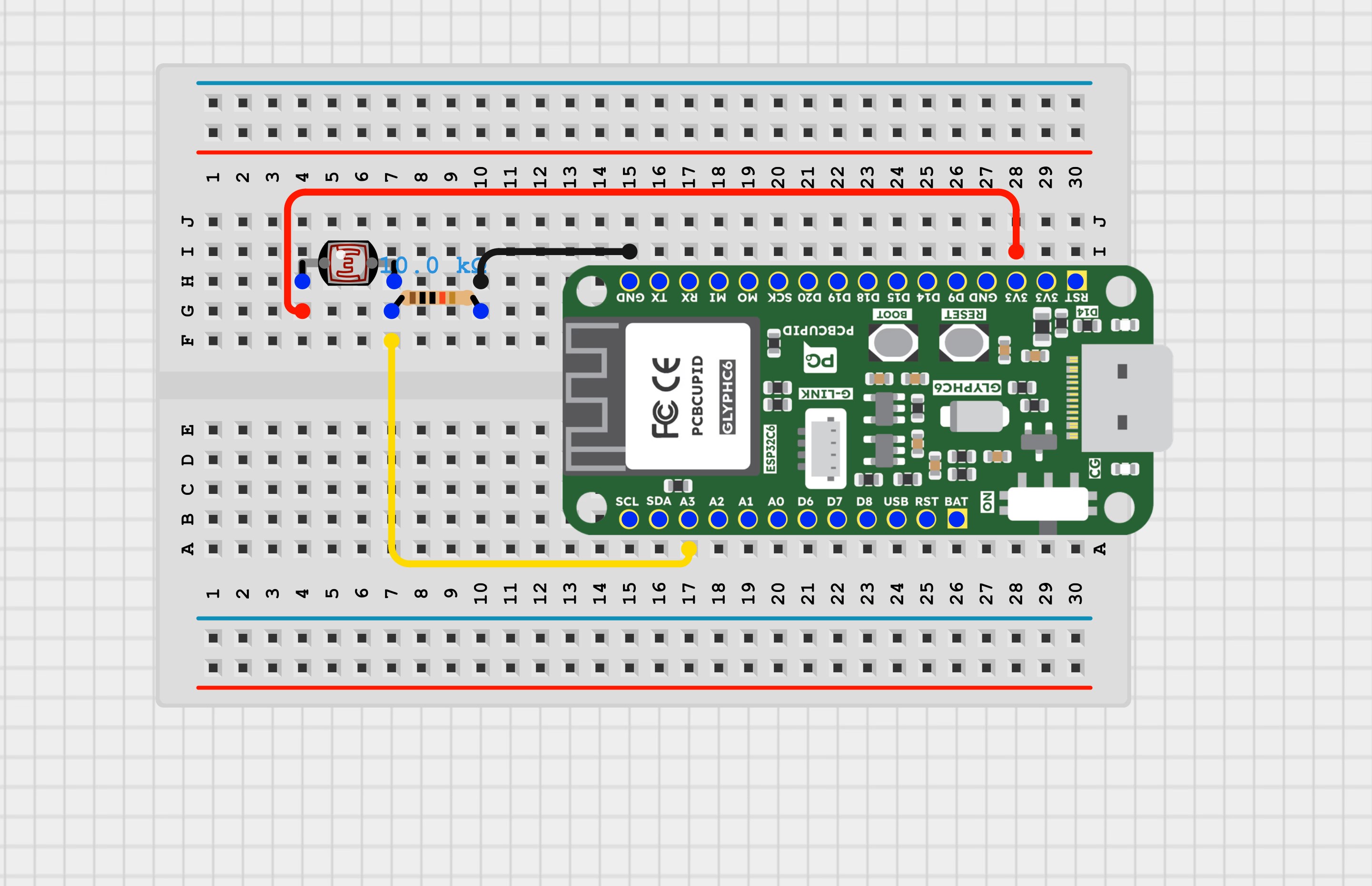
## Step 2: Circuit Diagram
## Step 3: Code Setup
```cpp theme={null}
#define LIGHT_SENSOR_PIN 3 // GLYPH-C6 pin GPIO 3 (ADC channel)
void setup()
{
// initialize serial communication at 115200 bits per second:
Serial.begin(115200);
// set the ADC attenuation to 11 dB (up to ~3.3V input)
analogSetAttenuation(ADC_11db);
}
void loop()
{
// reads the input on analog pin (value between 0 and 4095)
int analogValue = analogRead(LIGHT_SENSOR_PIN);
Serial.print("Analog Value = ");
Serial.print(analogValue); // the raw analog reading
// We'll have a few thresholds, qualitatively determined
if (analogValue < 40)
{
Serial.println(" => Dark");
}
else if (analogValue < 800)
{
Serial.println(" => Dim");
}
else if (analogValue < 2000)
{
Serial.println(" => Light");
}
else if (analogValue < 3200)
{
Serial.println(" => Bright");
}
else
{
Serial.println(" => Very bright");
}
delay(100);
}
```
## Step 4: Upload the Code
1. **Connect the Board**
* Connect your GLYPH board to your computer
2. **Select the Board and Port**
Do the following settings in your Arduino IDE,
* Tools > Board > esp32 > Pcbcupid GLYPH C6
For the `Pcbcupid GLYPH C6` to appear under Tools > Board > esp32, the esp32 board version installed in the Arduino IDE should be greater or equal to 3.1.0.
* Tools > Port and select the port connected to your GLYPH.
* Tools > USB CDC on Boot > **Enabled**
If USB CDC on BOOT is not enabled, you won't see any serial data in the Arduino IDE.
3. **Upload the Code**
Upload the corresponding code for your board to the GLYPH board using the Arduino IDE.
* Click the upload button (➡ icon) or use the shortcut CTRL + U in Arduino IDE to upload the code to the board.
## Step 5: Observe the Serial Monitor Output
Try covering and uncovering the LDR with your hand to block and pass light, and observe the output on the Serial Monitor.