> ## Documentation Index
> Fetch the complete documentation index at: https://learn.pcbcupid.com/llms.txt
> Use this file to discover all available pages before exploring further.
> Interface the ultra-low-power T5848 I2S MEMS microphone module with the Pcbcupid GLYPH-C3 board using native ESP32 I2S drivers, featuring Acoustic Activity Detect (AAD), WAKE, THSEL, and 1.8V pads.
# Single-Channel I2S Microphone (T5848)
export const ShopHeader = ({title, url}) =>
;
};
The **G-Sense Single-Channel Microphone (T5848)** is a high-performance, bottom-port digital I2S MEMS microphone module powered by the **TDK InvenSense T5848** IC. Designed specifically for always-on voice recognition, keyword spotting, edge AI, and ultra-low-power IoT applications, it combines studio-quality dynamic range with ground-breaking power efficiency.
Unlike traditional MEMS microphones, the T5848 includes built-in hardware **Acoustic Activity Detect (AAD)**. This feature monitors the acoustic environment while sipping as little as **20 µA**, instantly waking your microcontroller from deep sleep via the dedicated **WAKE** interrupt pad whenever sound is detected.
***
## Pin Configuration
The module exposes a 6-pin main connection header for standard I2S communication, along with dedicated auxiliary solder pads on the PCB for advanced power and wake features.
### Main Header Pinout
| Pin | Type | Function | Connection on GLYPH-C3 |
| :------ | :----- | :--------------------------------------------------- | :--------------------- |
| **VCC** | Power | Module supply input (3.3V or 1.8V) | **3.3V** |
| **GND** | Power | Common ground | **GND** |
| **SCK** | Input | I²S Serial Bit Clock (BCLK) | **GPIO 6** (MO) |
| **WS** | Input | I²S Word Select / Frame Sync (LRCK) | **GPIO 20** (RX) |
| **SD** | Output | I²S Serial Audio Data Output | **GPIO 7** (MI) |
| **LR** | Input | Left/Right Channel Select (LOW = Left, HIGH = Right) | **GPIO 21** (TX) |
### Additional Solder Pads on PCB
The PCB features three dedicated breakout solder pads for low-power edge computing and custom power configurations:
| Solder Pad | Function & Description |
| :--------- | :--------------------------------------------------------------------------------------------------------------------------------------------------------------------------------------------------------------------------------- |
| **WAKE** | **Acoustic Activity Detect (AAD) Interrupt**: Active-high output signal that flags acoustic energy detection. Connect this pad to an external interrupt or RTC wake-up GPIO on the GLYPH board to wake the system from deep sleep. |
| **THSEL** | **Threshold Select**: Configures the acoustic detection threshold / sensitivity of the AAD engine, determining the sound pressure level required to trigger the WAKE pin. |
| **1V8** | **1.8V Power Rail**: Direct access to the microphone's native 1.8V operating rail, enabling true ultra-low-power operation and direct compatibility with 1.8V low-power microcontrollers and sensor hubs. |
***
## Key Features
* **TDK InvenSense T5848 MEMS IC**: Cutting-edge multi-mode digital microphone with bottom acoustic port.
* **Direct I²S Digital Audio**: Connects straight to the ESP32 without requiring an external audio codec or analog circuitry.
* **Ultra-Low-Power Acoustic Activity Detect (AAD)**: Listens for sound and voices in edge-processing mode at just **20 µA**.
* **Hardware WAKE & THSEL Pads**: Easily trigger wake-up interrupts on voice/tap events with configurable detection thresholds.
* **1.8V Native Rail Breakout**: Dedicated solder pad for 1.8V power rails and energy-harvesting IoT nodes.
* **High Acoustic Overload Point (AOP)**: Up to 133 dB SPL, preventing distortion in noisy and high-volume environments.
* **High Signal-to-Noise Ratio (SNR)**: 68 dBA in High Quality Mode for clean speech recognition and audio recording.
* **Multi-Mode Power Management**: High Quality, Low Power (AlwaysOn), and Sleep modes with minimal latency.
***
## Application
* **Voice-Activated IoT Nodes**: Wake-on-sound home automation and smart assistants.
* **Keyword Spotting & Edge AI**: On-device voice classification with ESP32-C3 / ESP-SR.
* **Security & Glass Break Detection**: Acoustic event triggers using the hardware AAD engine.
* **Audio Recorders & Smart Wearables**: Low-power audio capture and sound monitoring.
* **Industrial Condition Monitoring**: Acoustic anomaly detection in rotating machinery.
***
## Step 1: Hardware Required
1. [Pcbcupid GLYPH-C3](https://shop.pcbcupid.com/product/gd001/) board (or any GLYPH ESP32 series board)
2. G-Sense 1-Channel Microphone (T5848) Module
3. Breadboard & Jumper wires
4. USB-C Cable for power and serial programming
***
## Step 2: Circuit Diagram

Connect the module to the **GLYPH-C3** as follows:
* **VCC** → GLYPH-C3 **3.3V**
* **GND** → GLYPH-C3 **GND**
* **SCK** → GLYPH-C3 **GPIO 6** (MO)
* **WS** → GLYPH-C3 **GPIO 20** (RX)
* **SD** → GLYPH-C3 **GPIO 7** (MI)
* **LR** → GLYPH-C3 **GPIO 21** (TX) *(driven LOW in software for Left Channel)*
*(Optional)*: Connect the **WAKE** solder pad to an available GPIO (e.g., GPIO 3) if utilizing wake-on-sound interrupts.
***
## Step 3: Code Setup
Open the Arduino IDE and paste the following sketch. This sketch uses the native ESP-IDF I2S driver built into the ESP32 Arduino Core to configure the master I2S receiver, read 32-bit digital audio samples from the T5848, and print sample amplitudes to the Serial Monitor:
```cpp theme={null}
#include
#define I2S_SCK_PIN 6 // MO
#define I2S_WS_PIN 20 // RX
#define I2S_SD_PIN 7 // MI
#define LR_PIN 21 // TX
#define SAMPLE_RATE 16000
#define I2S_PORT I2S_NUM_0
void setupI2S() {
i2s_config_t i2s_config = {
.mode = (i2s_mode_t)(I2S_MODE_MASTER | I2S_MODE_RX),
.sample_rate = SAMPLE_RATE,
.bits_per_sample = I2S_BITS_PER_SAMPLE_32BIT,
.channel_format = I2S_CHANNEL_FMT_ONLY_LEFT,
.communication_format = I2S_COMM_FORMAT_STAND_I2S,
.intr_alloc_flags = ESP_INTR_FLAG_LEVEL1,
.dma_buf_count = 4,
.dma_buf_len = 256,
.use_apll = false,
.tx_desc_auto_clear = false,
.fixed_mclk = 0
};
i2s_pin_config_t pin_config = {
.bck_io_num = I2S_SCK_PIN,
.ws_io_num = I2S_WS_PIN,
.data_out_num = I2S_PIN_NO_CHANGE,
.data_in_num = I2S_SD_PIN
};
esp_err_t r1 = i2s_driver_install(I2S_PORT, &i2s_config, 0, NULL);
esp_err_t r2 = i2s_set_pin(I2S_PORT, &pin_config);
Serial.printf("i2s_driver_install=%d i2s_set_pin=%d\n", r1, r2);
i2s_zero_dma_buffer(I2S_PORT);
}
void setup() {
Serial.begin(115200);
delay(500);
pinMode(LR_PIN, OUTPUT);
digitalWrite(LR_PIN, LOW); // selects left channel
setupI2S();
Serial.println("T5848 mic ready. Tap/blow on the mic now.");
}
void loop() {
int32_t buffer[8];
size_t bytesRead = 0;
i2s_read(I2S_PORT, buffer, sizeof(buffer), &bytesRead, portMAX_DELAY);
static uint32_t lastPrint = 0;
if (millis() - lastPrint > 500) {
lastPrint = millis();
Serial.printf("bytesRead=%d raw samples: %ld %ld %ld %ld\n",
bytesRead, buffer[0], buffer[1], buffer[2], buffer[3]);
}
}
```
***
## Step 4: Upload the Code
1. Connect your **GLYPH-C3** to your computer via USB-C.
2. In the Arduino IDE, configure the board settings:
* Go to **Tools → Board → esp32 → Pcbcupid GLYPH C3**.
For **Pcbcupid GLYPH C3** to appear under `Tools > Board > esp32`, the esp32 board package installed in the Arduino IDE must be **version 3.1.0 or higher**.
* Select your COM port under **Tools → Port**.
* Set **Tools → USB CDC On Boot → Enabled**.
If `USB CDC on Boot` is disabled, serial debug messages will not appear in the Serial Monitor.
3. Click **Upload** (or press `Ctrl + U`).
***
## Step 5: Observe the Output
1. Once uploaded, open the **Serial Monitor** at **115200 baud**.
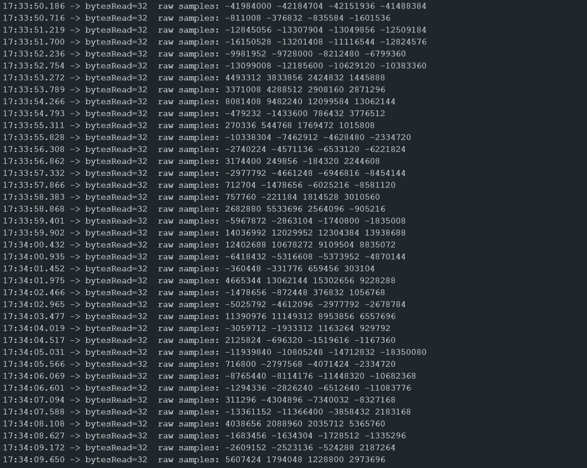
2. You will see the initialization status followed by the live 32-bit sample values:
 }
}