> ## Documentation Index
> Fetch the complete documentation index at: https://learn.pcbcupid.com/llms.txt
> Use this file to discover all available pages before exploring further.
> A serial flash module provides reliable non-volatile memory for microcontrollers, allowing for firmware storage, data logging, and configuration management.
# Serial Flash
export const ShopHeader = ({title, url}) =>
;
};
A **Serial Flash** Module is a compact memory device designed to interface a microcontroller (e.g., Arduino, ESP32, GLYPH, STM32) for non-volatile data storage, firmware storage, logging, and configuration management. Unlike SD cards, Serial Flash is directly soldered onto the board and communicates typically over SPI (and sometimes QSPI) for high-speed data transfer.
## Pin Configuration
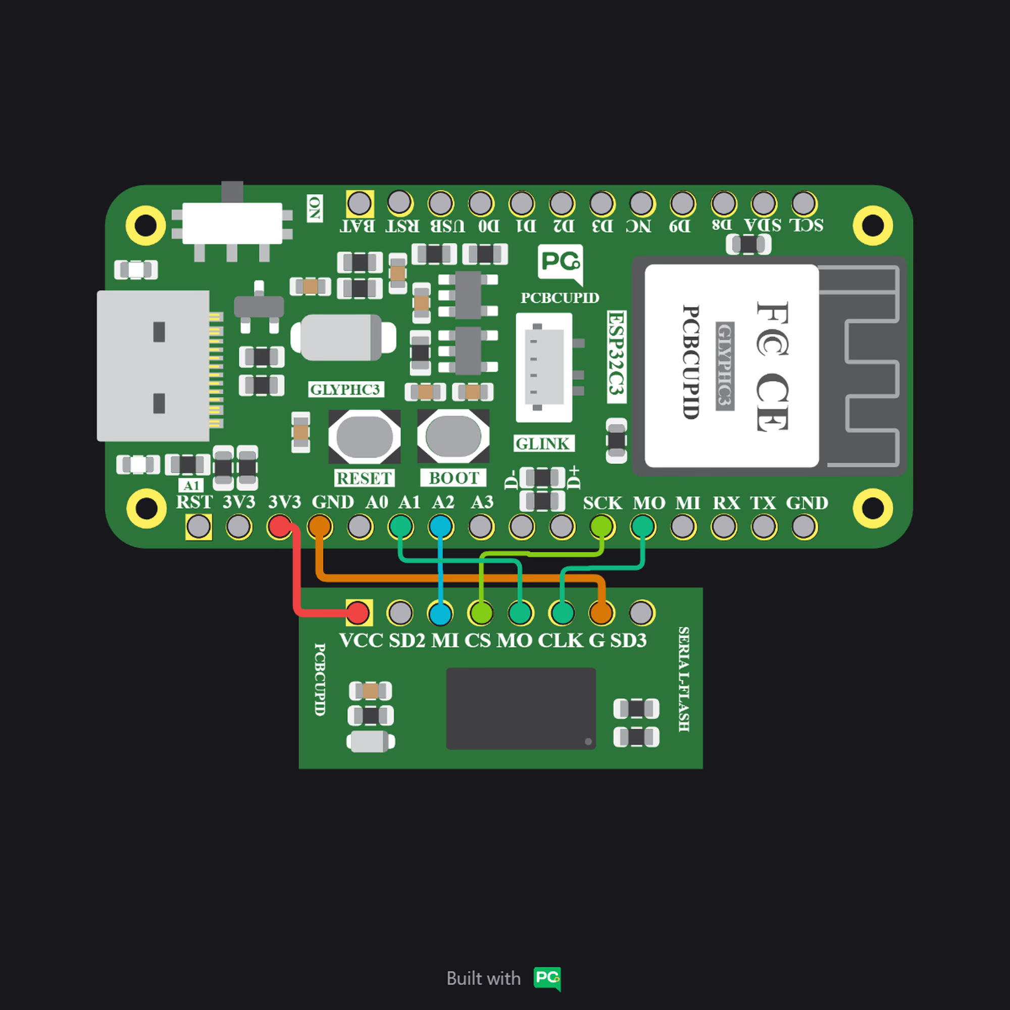
* VCC: Power supply input for the Serial Flash chip (typically 3.3V).
* G (GND): Ground .
* CLK: Serial Clock input for SPI communication
* CS: Chip Select (active LOW). Enables communication with the Serial Flash device.
* MO (MOSI / SI): Master Out Slave In — carries data from the
* MI (MISO / SO): Master In Slave Out — carries data from the Serial Flash to the microcontroller.
* SD2 (IO2): Data line 2. Used in Quad-SPI (QSPI) mode for higher-speed data transfer. In standard SPI mode, this pin is typically unused or acts as a hold function depending on the chip.
* SDI3 (IO3): Data line 3. Used in Quad-SPI (QSPI) mode. In standard SPI mode, this pin may function as Write Protect (WP) or Hold depending on the flash device.
## Key Features
* Non-volatile memory (retains data without power)
* SPI / QSPI communication support
* High-speed data transfer
* Compact and small footprint
* Low power consumption
* High endurance (multiple erase/write cycles)
* Sector and block erase capability
* Supports execute-in-place (XIP) in QSPI
* Wide voltage operating range (typically 3.3V)
* Reliable long-term data storage
## Application
* Firmware Storage: Storing bootloader, application code, or external program memory in embedded systems.
* OTA Updates: Holding firmware files for over-the-air updates in IoT devices.
* Data Logging: Recording sensor readings, event logs, or system data in real-time applications.
* Configuration Storage: Saving device settings, calibration values, or user preferences.
* Buffer Memory: Temporary storage for data processing in communication or control systems.
* Embedded Systems: Expanding memory capacity in microcontroller-based designs.
## Step 1: Hardware Required
1. Glyph Boards
2. G-MOD Serial flash Module
## Step 2: Circuit Diagram
## Step 3: Code Setup
1. **Open Arduino IDE.**
2. **Copy and paste the following code into the Arduino IDE:**
Here’s your code with detailed comments added so it’s easier to follow and understand:
```cpp theme={null}
#include
// Define the pin connections for the external SPI Flash chip
#define FLASH_CS 5 // Chip Select (CS) pin
#define FLASH_MISO 4 // Master In Slave Out (MISO) pin
#define FLASH_MOSI 7 // Master Out Slave In (MOSI) pin
#define FLASH_CLK 6 // Clock (SCK) pin
// Create an SPI object for FSPI (ESP32-C3 supports FSPI hardware bus)
SPIClass SPI1(FSPI);
void setup() {
Serial.begin(115200);
delay(1000);
Serial.println("ESP32-C3 SPI Flash Test");
pinMode(FLASH_CS, OUTPUT);
digitalWrite(FLASH_CS, HIGH);
SPI1.begin(FLASH_CLK, FLASH_MISO, FLASH_MOSI, FLASH_CS);
SPI1.beginTransaction(SPISettings(1000000, MSBFIRST, SPI_MODE0));
// Read JEDEC ID
readJEDEC();
// Write and Read Test Data
writeData(0x000000, "Hello Flash!");
delay(100);
readData(0x000000, 12);
}
void loop() {
// Nothing here
}
// ---------------- JEDEC READ ----------------
void readJEDEC() {
digitalWrite(FLASH_CS, LOW);
SPI1.transfer(0x9F);
byte mfg = SPI1.transfer(0x00);
byte type = SPI1.transfer(0x00);
byte size = SPI1.transfer(0x00);
digitalWrite(FLASH_CS, HIGH);
Serial.print("Manufacturer ID: 0x");
Serial.println(mfg, HEX);
Serial.print("Memory Type: 0x");
Serial.println(type, HEX);
Serial.print("Memory Size: 0x");
Serial.println(size, HEX);
}
// ---------------- WRITE ENABLE ----------------
void writeEnable() {
digitalWrite(FLASH_CS, LOW);
SPI1.transfer(0x06);
digitalWrite(FLASH_CS, HIGH);
}
// ---------------- WRITE DATA ----------------
void writeData(uint32_t address, const char* data) {
writeEnable();
digitalWrite(FLASH_CS, LOW);
SPI1.transfer(0x02); // Page Program
SPI1.transfer((address >> 16) & 0xFF);
SPI1.transfer((address >> 8) & 0xFF);
SPI1.transfer(address & 0xFF);
while (*data) {
SPI1.transfer(*data++);
}
digitalWrite(FLASH_CS, HIGH);
delay(10);
}
// ---------------- READ DATA ----------------
void readData(uint32_t address, int length) {
digitalWrite(FLASH_CS, LOW);
SPI1.transfer(0x03);
SPI1.transfer((address >> 16) & 0xFF);
SPI1.transfer((address >> 8) & 0xFF);
SPI1.transfer(address & 0xFF);
Serial.print("Data Read: ");
for (int i = 0; i < length; i++) {
char c = SPI1.transfer(0x00);
Serial.print(c);
}
digitalWrite(FLASH_CS, HIGH);
Serial.println();
}
```
## Step 4: Upload the Code
1. **Connect the Board**
* Connect your GLYPH board to your computer
2. **Select the Board and Port**
Do the following settings in your Arduino IDE,
* `Tools > Board > esp32 > Pcbcupid GLYPH C3`
For the `Pcbcupid Glyph C3 ` to appear under `Tools > Board > esp32`, the esp32 board version installed in the Arduino IDE should be greater or equal to 3.1.0.
* `Tools > Port` and select the port connected to your GLYPH.
* `Tools > USB CDC on Boot >` ***Enabled***
If `USB CDC on BOOT` not enabled, you won't be seeing any serial data on Arduino IDE.
3. **Upload the Code**
* Click the upload button (➡️ icon) or use the shortcut `CRTL + U` in Arduino IDE to upload the code to the board.
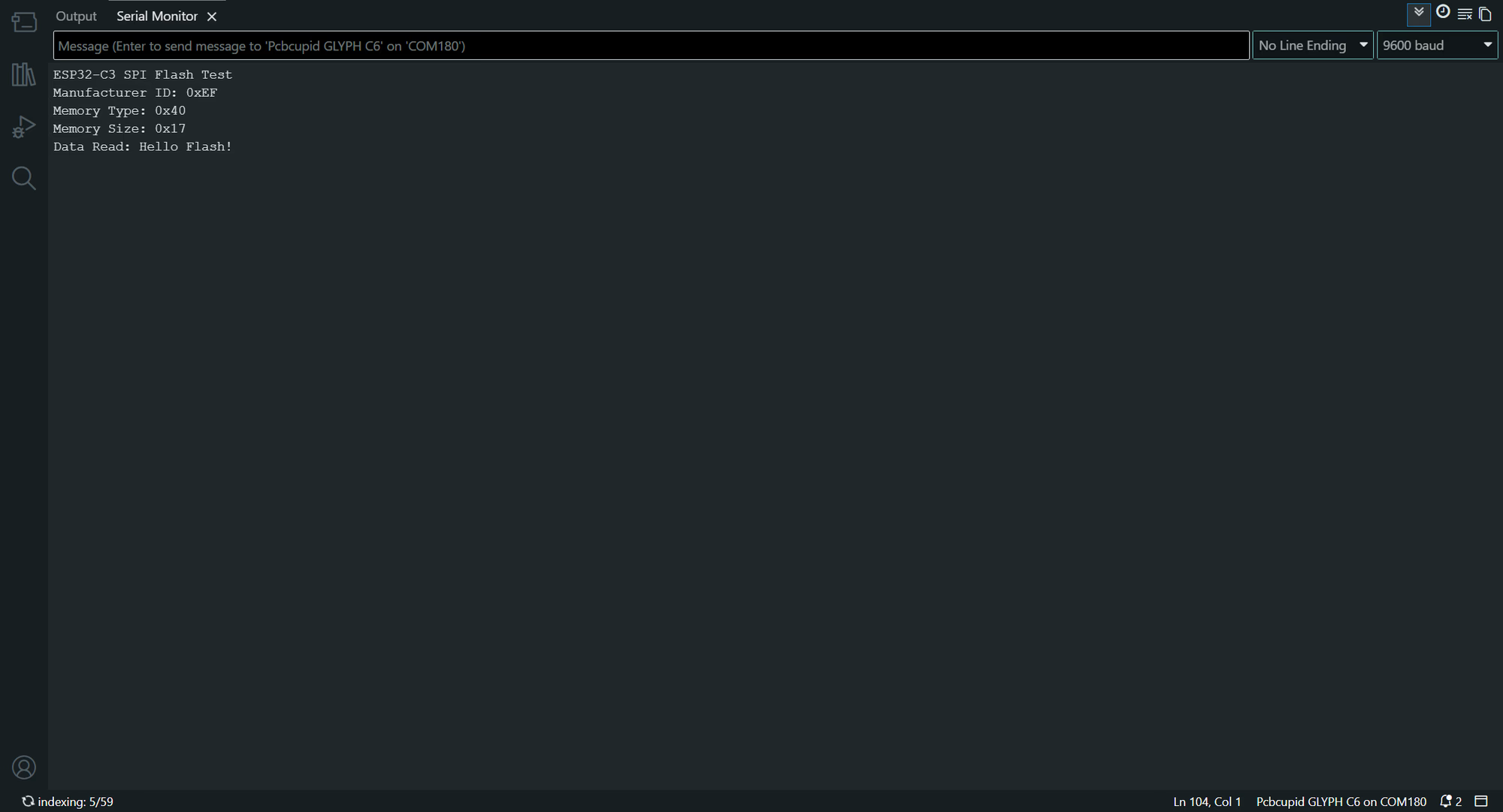
## Step 5: Observe Output on Serial Monitor
 }
}