> ## Documentation Index
> Fetch the complete documentation index at: https://learn.pcbcupid.com/llms.txt
> Use this file to discover all available pages before exploring further.
> Wire the G-Mod 2-channel relay module to a Glyph ESP32 development board and switch two independent high-voltage loads from Arduino digital pins.
# 2-Channel Relay
export const ShopHeader = ({title, url}) =>
;
};
A **2-channel relay** for controlling two independent high-power loads simultaneously using low-power control signals from microcontrollers like Arduino, [GLYPH](https://shop.pcbcupid.com/product-category/development-boards/), or even Raspberry Pi. Here's how it works:
### Components
* Two Relays: Each relay can independently control a high-power (Both AC / DC) device.
* Control Pins: There are two input pins (IN1 and IN2) for controlling each relay.
* Power Supply: A single power source is used for both relays **5V**
* Protection : Has 2 Optocoupler to electrical isolation between the control and relay circuits for both channels.
### Pin Configuration
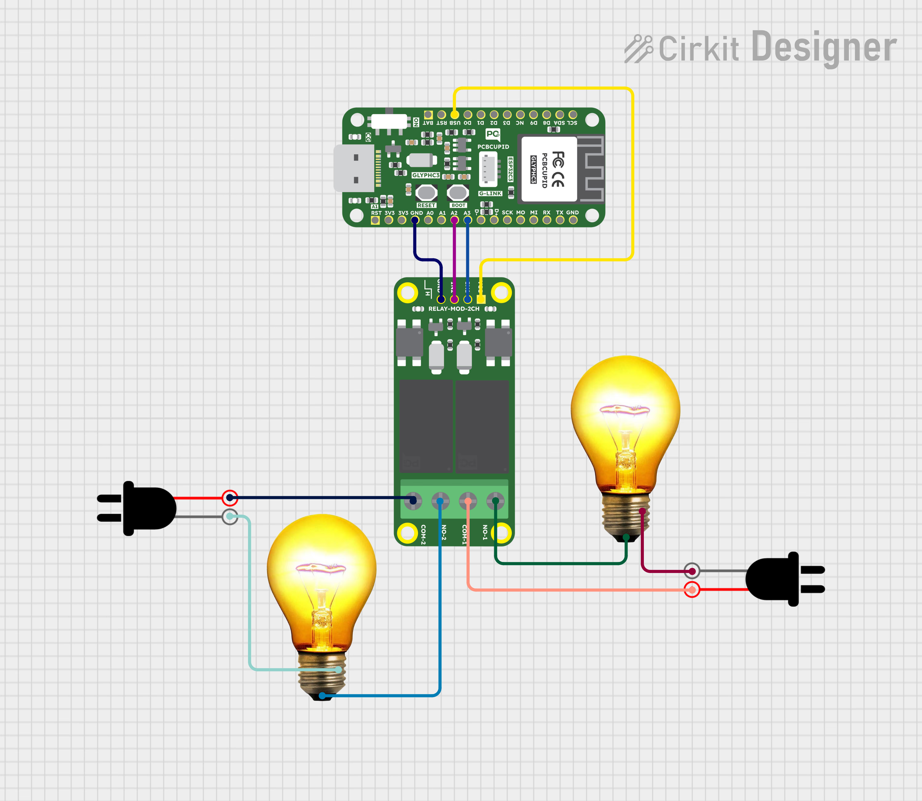
* VCC: Power supply for the module (5V).
* GND: Ground connection.
* IN1: Control signal for Relay 1.
* IN2: Control signal for Relay 2.
* COM1, NO1: Relay 1 switching terminals.
* COM2, NO2: Relay 2 switching terminals.
### Relay Contacts
* COM (Common): The input terminal.
* NO (Normally Open): Open by default, closes when the relay is activated.
### Working
* Each relay channel works independently, following the same principles as a single-channel relay:
* When Control Signal is LOW (0V):
The associated transistor remains off.
The corresponding relay coil is de-energized.
The relay's Normally Open (NO) contact stays open, and the Normally Closed (NC) contact remains closed.
* When Control Signal is HIGH (3.3V/5V):
The associated transistor turns on, allowing current to flow through the relay coil.
The coil energizes, creating a magnetic field that pulls the armature.
The relay's NO contact closes, completing the circuit for the connected load, while the NC contact opens.
* Operation Sequence for Two Relays
* IN1 HIGH: Activates Relay 1 to control Load 1.
* IN2 HIGH: Activates Relay 2 to control Load 2.
* Both IN1 and IN2 HIGH: Activates both relays simultaneously to control both loads.
* Both IN1 and IN2 LOW: Deactivates both relays, disconnecting both loads.
### Applications
* Home Automation: Controlling lights and fans independently.
* Industrial Automation: Managing two separate devices or motors.
* DIY Projects: Operating appliances remotely with microcontroller-based projects.
This guide will help you interface a 2 Channel Relay assuming you are using [GLYPH-C3](https://learn.pcbcupid.com/boards/glyph-c3/overview)(but any [GLYPH development board](https://shop.pcbcupid.com/product-category/development-boards/) from the ESP32 Series should work)
## Step 1: Hardware Required
1. Glyph Board
2. GMOD 2 Channel Relay Module
## Step 2: Circuit Diagram
## Step 3: Code Setup
1. **Open Arduino IDE.**
2. **Copy and paste the following code into the Arduino IDE:**
```cpp theme={null}
// Pin definitions for 2-Channel Relay Module
const int RELAY_1 = 3; // GPIO2 for first relay
const int RELAY_2 = 2; // GPIO3 for second relay
void setup()
{
// Initialize serial communication
Serial.begin(115200);
// Configure relay pins as outputs
pinMode(RELAY_1, OUTPUT);
pinMode(RELAY_2, OUTPUT);
// Initialize Both Relay Channels to OFF state (relays are typically Active LOW- Means they are OFF when a HIGH Signal is Applied and vice-versa)
digitalWrite(RELAY_1, HIGH);
digitalWrite(RELAY_2, HIGH);
Serial.println("Relay Module Initialized"); //Print that Relay Module is Initialized
}
void loop()
{
// Example control sequence
// Turn ON Relay 1
digitalWrite(RELAY_1, LOW);
Serial.println("Turning on Relay 1");
delay(2000);
// Turn OFF Relay 1
digitalWrite(RELAY_1, HIGH);
Serial.println("Turning off Relay 1");
delay(1000);
// Turn ON Relay 2
digitalWrite(RELAY_2, LOW);
Serial.println("Turning on Relay 2");
delay(2000);
// Turn OFF Relay 2
digitalWrite(RELAY_2, HIGH);
Serial.println("Turning off Relay 2");
delay(1000);
}
// Helper functions for relay control
void turnOnRelay(int relayPin)
{
digitalWrite(relayPin, LOW);
}
void turnOffRelay(int relayPin)
{
digitalWrite(relayPin, HIGH);
}
void toggleRelay(int relayPin)
{
digitalWrite(relayPin, !digitalRead(relayPin));
}
```
## Step 4: Upload the Code
1. **Connect the Board**
* Connect your GLYPH board to your computer
2. **Select the Board and Port**
Do the following settings in your Arduino IDE,
* `Tools > Board > esp32 > Pcbcupid GLYPH C3`
For the `Pcbcupid GLYPH C3 ` to appear under `Tools > Board > esp32`, the esp32 board version installed in the Arduino IDE should be greater than or equal to 3.1.0.
* `Tools > Port` and select the port connected to your GLYPH.
* `Tools > USB CDC on Boot >` ***Enabled***
If `USB CDC on BOOT` is not enabled, you won't be seeing any serial data on Arduino IDE.
3. **Upload the Code**
* Click the upload button (➡️ icon) or use the shortcut `CTRL + U` in Arduino IDE to upload the code to the board.
## Step 5: Observe the Output
On Serial Monitor, you should see the output like this:
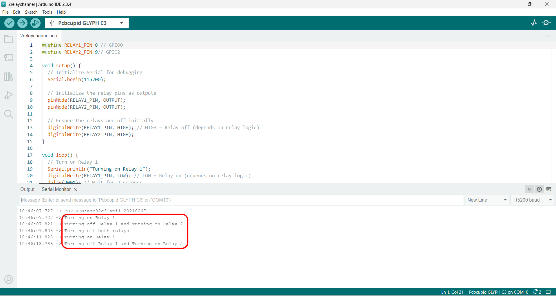
Along with this you should see the relay ticking and corresponding LED blink.
 }
}