> ## Documentation Index
> Fetch the complete documentation index at: https://learn.pcbcupid.com/llms.txt
> Use this file to discover all available pages before exploring further.
> The G-Mod TB6612FNG dual motor driver controls two DC motors via an integrated dual H-bridge IC for efficient bidirectional speed and direction control.
# Dual Motor Driver
export const ShopHeader = ({title, url}) =>
;
};
The **GMOD TB6612FNG Dual Motor Driver** is a high-efficiency power control module designed to drive up to two DC motors or one bipolar stepper motor. Built around the advanced **TB6612FNG** dual H-bridge IC, it provides superior efficiency and lower heat generation compared to older drivers like the L298N.
This module allows for precise bidirectional control (Forward/Reverse) and speed regulation using PWM signals, making it an essential component for robotics, automated vehicles, and high-performance embedded systems.
***
## Key Features
* **Dual Channel Control**: Independently drives two DC motors or one bipolar stepper motor.
* **High Efficiency**: MOSFET-based H-bridge design for minimal voltage drop and low heat.
* **Built-in Protection**: Includes over-current protection, thermal shutdown, and low-voltage detection.
* **Standard Control Logic**: Compatible with most microcontrollers via PWM and simple direction pins.
* **Compact G-Mod Format**: Plugs directly into Glyph development boards.
***
## Technical Specifications
| Parameter | Operating Range |
| :-------------------------- | :------------------------------ |
| **Motor Supply (VM)** | 2.5V – 13.5V DC |
| **Logic Supply (VCC)** | 2.7V – 5.5V DC |
| **Output Current** | 1.2A (Continuous) / 3.2A (Peak) |
| **Switching Frequency** | Up to 100 kHz (PWM) |
| **Internal MOSFET RDS(on)** | 0.5Ω (Typical) |
***
## Pin Configuration
The module features a standard interface for motor power and control:
| Pin Name | Description |
| :-------------- | :-------------------------------------------------------- |
| **VCC** | Logic Logic Power (3.3V / 5V) |
| **GND** | Ground (Common for Logic and Power) |
| **VM** | External Motor Power Source (2.5V – 13.5V) |
| **STBY** | Standby Control (**HIGH** = Enable, **LOW** = Power Down) |
| **AIN1 / AIN2** | Direction Control inputs for Motor A |
| **PWMA** | PWM input for Speed Control of Motor A |
| **BIN1 / BIN2** | Direction Control inputs for Motor B |
| **PWMB** | PWM input for Speed Control of Motor B |
| **AO1 / AO2** | Output terminals for Motor A |
| **BO1 / BO2** | Output terminals for Motor B |
***
## H-Bridge Control Logic
Both channels (A and B) follow the same truth table for controlling movement:
| STBY | IN1 | IN2 | PWM | Output (O1 / O2) | Motor Mode |
| :------- | :------- | :------- | :------- | :--------------- | :---------------- |
| **LOW** | X | X | X | High-Z | **Standby (OFF)** |
| **HIGH** | **HIGH** | **LOW** | **HIGH** | H / L | **Forward** |
| **HIGH** | **LOW** | **HIGH** | **HIGH** | L / H | **Reverse** |
| **HIGH** | **HIGH** | **HIGH** | X | L / L | **Short Brake** |
| **HIGH** | **LOW** | **LOW** | X | High-Z | **Stop (Coast)** |
***
## Step 1: Hardware Required
1. GMOD TB6612FNG Motor Driver
2. [GLYPH (ESP32-S3 / C3 / C6)](https://shop.pcbcupid.com/product-category/development-boards/)
3. 2x DC Motors
4. External Battery Pack (e.g., 7.4V Li-ion or 12V LiPo)
***
## Step 2: Circuit Connection
Connect the driver to your Glyph board following the GPIO definitions provided in your specific code example.
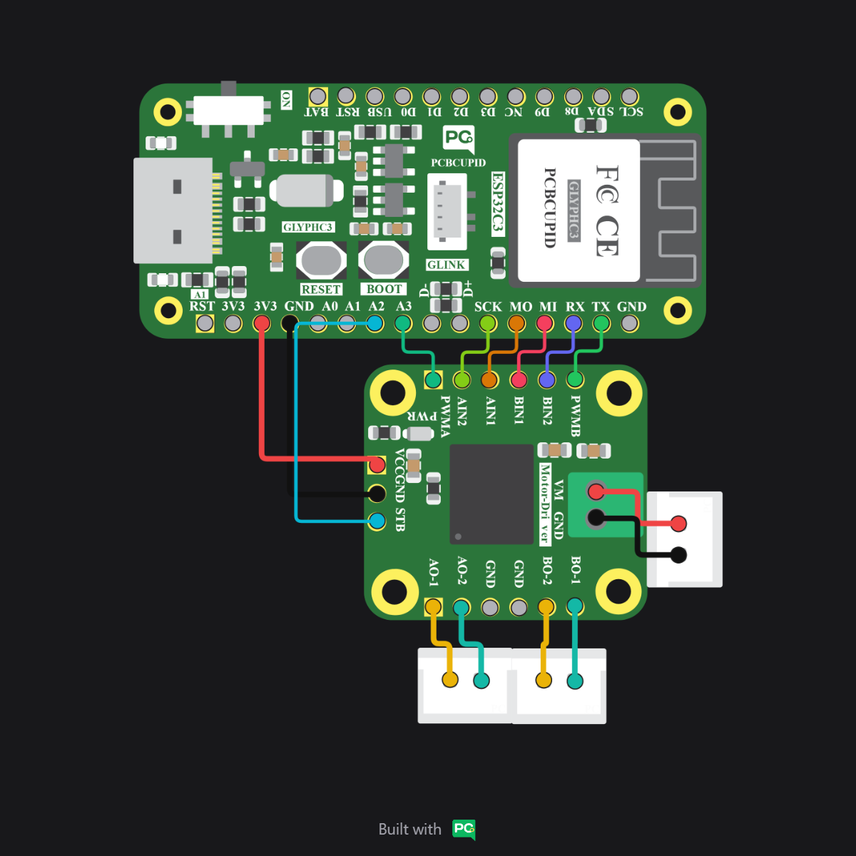
Always ensure the **VM (Motor Power)** and **VCC (Logic Power)** are not swapped, and that they share a common Ground (GND). Reversing polarity on VM can damage the TB6612FNG IC.
***
## Step 3: Code Setup
* **I2C Conflict**: GPIO 5 is the default **SCL** pin for I2C communication across the entire **GLYPH series (C3, C6, and S3)**. If you are using I2C sensors via the GLINK port, change the `STBY` pin in the code to an alternative digital pin (e.g., GPIO 6 or 14) to avoid communication conflicts.
* **Standby vs. Coast**: Setting `STBY` to `LOW` puts the driver in **Standby** (Power Down). For a true **Coast** stop where the motor spins freely, keep `STBY` HIGH and set both `AIN1` and `AIN2` to `LOW`.
```cpp theme={null}
// Mapping pins for TB6612FNG
const int STBY = 5; // Standby pin
const int AIN1 = 18; // Motor A Direction 1
const int AIN2 = 19; // Motor A Direction 2
const int PWMA = 21; // Motor A Speed (PWM)
void setup() {
pinMode(STBY, OUTPUT);
pinMode(AIN1, OUTPUT);
pinMode(AIN2, OUTPUT);
pinMode(PWMA, OUTPUT);
// Enable the driver
digitalWrite(STBY, HIGH);
}
void loop() {
// Move Forward at half speed
digitalWrite(AIN1, HIGH);
digitalWrite(AIN2, LOW);
analogWrite(PWMA, 127); // Range 0-255
delay(2000);
// Stop (Short Brake)
digitalWrite(AIN1, HIGH);
digitalWrite(AIN2, HIGH);
delay(1000);
// Reverse at full speed
digitalWrite(AIN1, LOW);
digitalWrite(AIN2, HIGH);
analogWrite(PWMA, 255);
delay(2000);
// Coast Stop
digitalWrite(STBY, LOW); // Disable driver
delay(1000);
digitalWrite(STBY, HIGH); // Re-enable
}
```
***
## Step 4: Upload the Code
1. **Connect the Board**
* Connect your GLYPH board to your computer via USB.
2. **Select the Board and Port**
In the Arduino IDE:
* Select `Tools > Board > esp32 > Pcbcupid GLYPH`.
* Select `Tools > Port` and choose the port connected to your board.
* Ensure `Tools > USB CDC on Boot` is set to **Enabled**.
3. **Upload**
* Click the **Upload** button (or press `CTRL + U`) to compile and flash the code.
***
## Step 5: Observe the Output
Once the code is uploaded, the connected motors should rotate forward for 2 seconds, brake briefly, and then reverse for 2 seconds before coasting to a stop.
* **STBY Pin**: Remember that the STBY pin must be pulled **HIGH** for the motor driver to respond to any commands.
* **Common Ground**: Ensure the external motor power supply Ground is connected to the microcontroller Ground.
* **Thermal Check**: While the TB6612FNG is efficient, it may become warm when driving heavy loads. Ensure proper ventilation.
 }
}