> ## Documentation Index
> Fetch the complete documentation index at: https://learn.pcbcupid.com/llms.txt
> Use this file to discover all available pages before exploring further.
> MCP79412 RTC module with I²C, battery backup, alarms, and memory. Ideal for accurate timekeeping in Arduino, Raspberry Pi, and IoT projects.
# MCP79412 RTC
export const ShopHeader = ({title, url}) =>
;
};
The **MCP79412** from Microchip Technology is a low-power, I²C-based real-time clock/calendar (RTCC) with integrated EEPROM, SRAM, and a unique ID. It provides highly accurate timekeeping (seconds, minutes, hours, day, date, month, year) and includes alarm functions, power-fail timestamping, and battery backup support, making it ideal for applications that require reliable time and date tracking.
Check the back of the RTC module: modules marked **“M”** use the ***MCP79412***, while those marked **“P”** use the ***PCF8563***.
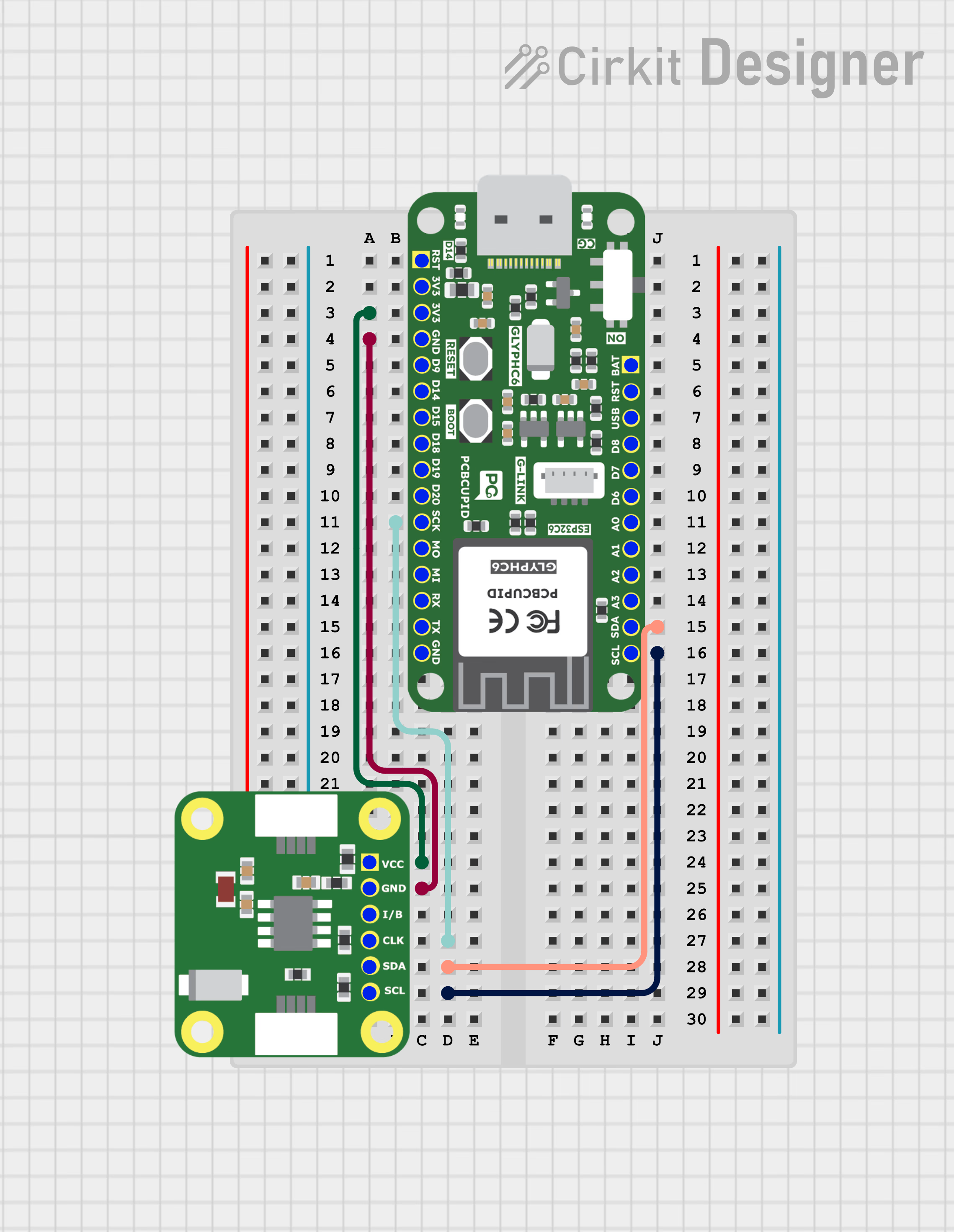
## Pin Configuration
* VCC → VCC
* GND → GND
* CLK → SCK / Any GPIO
* SDA → SDA
* SCL → SCL
* B → No connection / Internally connected to the 3V battery
Install a 3V Lithium Cell (CR1220) on the RTC module to retain time when the main circuit is powered off. The module can also operate without a battery if the circuit remains powered.
## Key Features
* I²C Interface (400 kHz Fast Mode)
* Timekeeping: seconds, minutes, hours, day, date, month, year with leap year compensation
* Two Alarms with programmable match options
* Battery Backup with automatic switchover
* Power-Fail Timestamp (records time of power loss)
* 64 Bytes SRAM + 1 Kbit EEPROM (non-volatile storage)
* Unique 64-bit ID (factory-programmed)
* Digital Trimming for oscillator accuracy adjustment
* Operating Voltage: 1.8V – 5.5V
* Temperature Range: −40 °C to +85 °C (industrial)
## Applications
* Data loggers and metering systems
* Security and access control devices
* Consumer electronics (appliances, clocks, timers)
* Automotive time-stamping and scheduling
* Embedded systems requiring alarms, scheduling, or backup timekeeping
## Step 1: Hardware Required
1. Glyph Boards
2. GMOD MCP79412 RTC
## Step 2: Circuit Diagram
## Step 3: Code Setup
1. **Open Arduino IDE.**
2. **Make sure to install the library**
3. **Copy and paste the following code into the Arduino IDE:**
```cpp theme={null}
// You can downlaod PCBCUPID_MCP79412 from here https://github.com/pcbcupid/PCBCUPID-MCP79412
#include
#include "PCBCUPID_MCP79412.h"
#include
PCBCUPID_MCP79412RTC rtc;
tmElements_t tm;
// Helper to read an integer cleanly from Serial, flushing leftover chars
int readIntFromSerial() {
while (!Serial.available()) {
delay(10);
}
int val = Serial.parseInt();
while (Serial.available()) Serial.read(); // flush
return val;
}
void setup()
{
Serial.begin(115200);
delay(1000);
Serial.println(F("\r\n=======PCBCUPID_MCP79412 RTC Test Menu ==========\r\n"));
Serial.println(F("0: Wire.begin() default pins\r\n1: Wire.begin(sda,scl,clockFreq)\r\n2: Wire.begin(TwoWire*)"));
Serial.println(F("Type 0-2 to select I2C init mode....."));
uint8_t mode =
readIntFromSerial();
// These are different way's to initialize the I2C of RTC module
switch (mode)
{
case 0:
rtc.begin();
Serial.println(F(">>>Wire.begin() with default pins\r\n"));
break;
case 1:
rtc.begin(4, 5, 400000); // ESP32 based glyph default SDA/SCL
Serial.println(F(">>>Wire.begin(4,5,400kHz)\r\n"));
break;
case 2:
rtc.begin(&Wire);
Serial.println(F(">>>Wire.begin() using custom Twowire instance\r\n"));
break;
default:
Serial.println(F("Invalid Input, using default Wire.begin()\r\n"));
Wire.begin();
}
Serial.println(F("**********RTC Function Modes*************"));
Serial.println(F("3. Set RTC using setTime() + now()"));
Serial.println(F("4. Set RTC using tmElements_t"));
Serial.println(F("5: Set RTC using compile time"));
Serial.println(F("Type 3-5 to select RTC mode..."));
mode = readIntFromSerial();
// below are the different mode to setup the time for the RTC module
switch (mode)
{
case 3:
setTime(3, 43, 45, 20, 5, 2025); // HH, MM, SS, DD, MM, YYYY
rtc.set(now());
Serial.println(F(">> RTC set using setTime() + now()\r\n"));
break;
case 4:
tm.Hour = 23;
tm.Minute = 31;
tm.Second = 30;
tm.Year = 2009 - 1970;
tm.Month = 5;
tm.Day = 20;
tm.Wday = dowTuesday;
rtc.write(tm);
Serial.println(F(">> RTC set using tmElements_t structure\r\n"));
break;
case 5:
setTime(compileTime());
rtc.set(now());
Serial.println(F(">> RTC set using sketch compile time\r\n"));
break;
default:
Serial.println(F("Invalid RTC mode, terminating.\r\n"));
while (true)
;
}
delay(500);
}
void loop()
{
Serial.println(F("\r\n--- Current Time ---"));
printTime(now());
if (rtc.read(tm))
{
Serial.print(F("RTC tmElements_t: "));
Serial.print(tm.Hour); Serial.print(':');
printI00(tm.Minute, ':');
printI00(tm.Second, ' ');
Serial.print(tm.Year + 1970);
Serial.print('/');
Serial.print(tm.Month);
Serial.print('/');
Serial.println(tm.Day);
}
else
{
Serial.println(F("Failed to read RTC time using .read()"));
}
delay(3000);
}
void printTime(time_t t)
{
printI00(hour(t), ':');
printI00(minute(t), ':');
printI00(second(t), ' ');
Serial.print(dayShortStr(weekday(t)));
Serial.print(' ');
printI00(day(t), ' ');
Serial.print(monthShortStr(month(t)));
Serial.print(' ');
Serial.println(year(t));
}
void printI00(int value, char delimiter)
{
if (value < 10)
Serial.print('0');
Serial.print(value);
Serial.print(delimiter);
}
time_t compileTime()
{
const char *months = "JanFebMarAprMayJunJulAugSepOctNovDec";
char monthstr[4];
tmElements_t tm;
strncpy(monthstr, __DATE__, 3);
monthstr[3] = '\0';
tm.Month = (strstr(months, monthstr) - months) / 3 + 1;
tm.Day = atoi(__DATE__ + 4);
tm.Year = atoi(__DATE__ + 7) - 1970;
char buf[3];
memcpy(buf, __TIME__, 2);
buf[2] = '\0';
tm.Hour = atoi(buf);
memcpy(buf, __TIME__ + 3, 2);
buf[2] = '\0';
tm.Minute = atoi(buf);
memcpy(buf, __TIME__ + 6, 2);
buf[2] = '\0';
tm.Second = atoi(buf);
return makeTime(tm) + 15; // fudge factor
}
```
## Step 4: Upload the Code
1. **Connect the Board**
* Connect your GLYPH board to your computer
2. **Select the Board and Port**
Do the following settings in your Arduino IDE,
* `Tools > Board > esp32 > Pcbcupid GLYPH C3`
For the `Pcbcupid Glyph C3 ` to appear under `Tools > Board > esp32`, the esp32 board version installed in the Arduino IDE should be greater or equal to 3.1.0.
* `Tools > Port` and select the port connected to your GLYPH.
* `Tools > USB CDC on Boot >` ***Enabled***
If `USB CDC on BOOT` not enabled, you won't be seeing any serial data on Arduino IDE.
3. **Upload the Code**
* Click the upload button (➡️ icon) or use the shortcut `CRTL + U` in Arduino IDE to upload the code to the board.
## Step 5: Observe the Output
The RTC module tracks time independently. With the onboard 3V Lithium Cell (CR1220), it continues timekeeping even when the GLYPH is powered off.

 }
}