> ## Documentation Index
> Fetch the complete documentation index at: https://learn.pcbcupid.com/llms.txt
> Use this file to discover all available pages before exploring further.
> 1×3 and 1×6 Push Button Module is a compact board with three independent tactile switches for providing digital input to microcontrollers.
# Key Array
export const ShopHeader = ({title, url}) =>
;
};
The **1×3 Push Button Module** is a simple input device that combines three tactile switches on a single board. It allows users to give manual digital inputs (ON/OFF signals) to a microcontroller. Each button works independently, making the module suitable for menu navigation, mode selection, or basic control functions in embedded projects.
### Pins Configuration
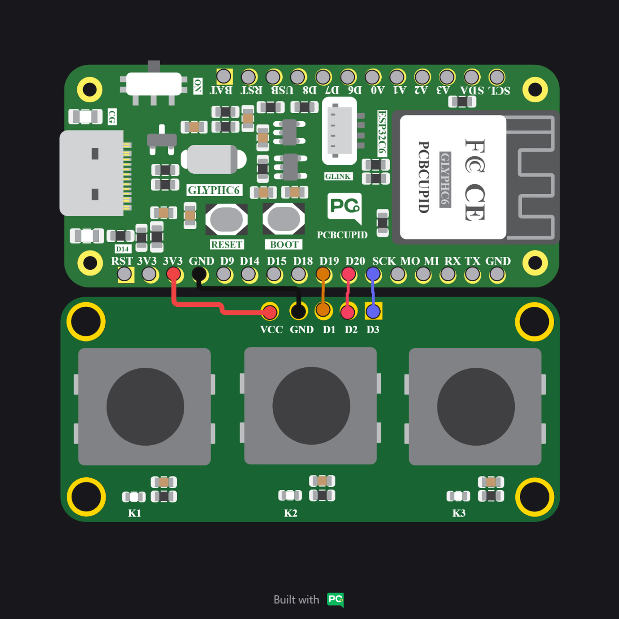
* VCC – Power supply (3.3V or 5V).
* GND – Ground.
* OUT1 – Digital signal from Button 1.
* OUT2 – Digital signal from Button 2.
* OUT3 – Digital signal from Button 3.
### Key Features
* Three independent push buttons on a single module.
* Designed with clear labeling for Button 1, Button 2, Button 3.
* Each button typically connected with a pull-down/pull-up resistor (depending on design).
* Standard 4-pin/5-pin header for easy interfacing.
### Applications
* Menu navigation (Up/Down/Select).
* Multi-option input control.
* Mode/Function selector in DIY electronics.
* Robotics control panels.
* Educational and prototyping projects.
### Step 1: Hardware Required
1. Glyph Boards
2. 1×3 Push Button Module
### Step 2: Circuit Diagram
### Step 3: Code Setup
1. **Open Arduino IDE.**
2. **Make sure to install the library**
3. **Copy and paste the following code into the Arduino IDE:**
```cpp theme={null}
// Define pins (each button shares the same pin as its LED)
int ledButton1 = 6;
int ledButton2 = 10;
int ledButton3 = 7;
void setup() {
Serial.begin(9600);
}
void loop() {
// --- Button 1 ---
pinMode(ledButton1, INPUT);
int state1 = digitalRead(ledButton1);
if (state1 == HIGH) {
Serial.println("Button 1 pressed → LED1 ON");
pinMode(ledButton1, OUTPUT);
digitalWrite(ledButton1, HIGH);
} else {
Serial.println("Button 1 not pressed → LED1 OFF");
pinMode(ledButton1, OUTPUT);
digitalWrite(ledButton1, LOW);
}
// --- Button 2 ---
pinMode(ledButton2, INPUT);
int state2 = digitalRead(ledButton2);
if (state2 == HIGH) {
Serial.println("Button 2 pressed → LED2 ON");
pinMode(ledButton2, OUTPUT);
digitalWrite(ledButton2, HIGH);
} else {
Serial.println("Button 2 not pressed → LED2 OFF");
pinMode(ledButton2, OUTPUT);
digitalWrite(ledButton2, LOW);
}
// --- Button 3 ---
pinMode(ledButton3, INPUT);
int state3 = digitalRead(ledButton3);
if (state3 == HIGH) {
Serial.println("Button 3 pressed → LED3 ON");
pinMode(ledButton3, OUTPUT);
digitalWrite(ledButton3, HIGH);
} else {
Serial.println("Button 3 not pressed → LED3 OFF");
pinMode(ledButton3, OUTPUT);
digitalWrite(ledButton3, LOW);
}
delay(100);
}
```
### Step 4: Upload the Code
1. **Connect the Board**
* Connect your GLYPH board to your computer
2. **Select the Board and Port**
Do the following settings in your Arduino IDE,
* `Tools > Board > esp32 > Pcbcupid GLYPH C3`
3. **Upload the Code**
* Click the upload button (➡️ icon) or use the shortcut `CRTL + U` in Arduino IDE to upload the code to the board.
### Step 5: Observe the Output
***
The **1×6 Key Array Module** is a compact input device that integrates six tactile switches on a single board. Unlike individual digital buttons, this module uses a resistor network to generate distinct analog voltage levels for each key. When a button is pressed, the microcontroller reads a specific analog value, allowing it to identify which key was selected through a single analog input pin. This makes the module efficient for menu navigation, option selection, and multi-button control in embedded systems while minimizing the number of GPIO pins required.
### Pins Configuration
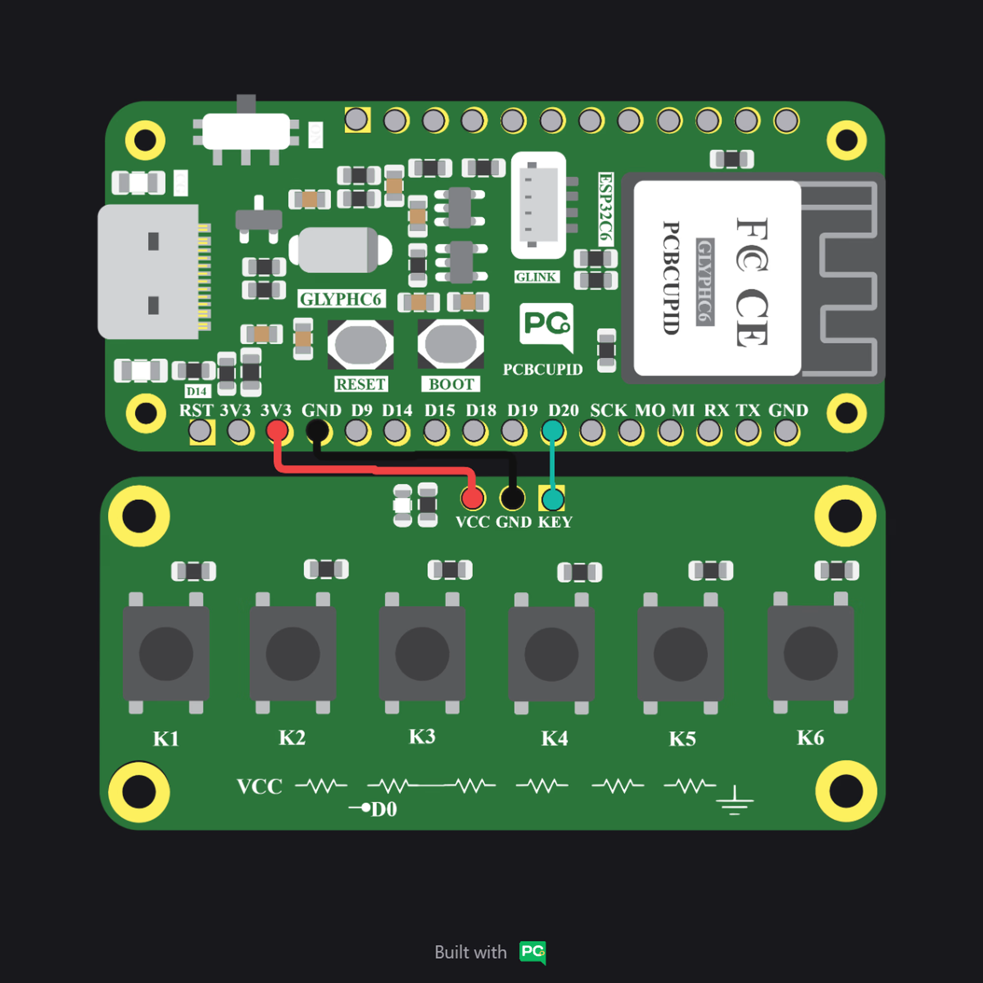
* VCC - Power supply (3.3V / 5V)
* GND - Ground
* KEY (Analog Output) – Analog signal representing the pressed button
### Key Features
* Six tactile switches on a single board
* Single analog output (KEY pin) for detecting all buttons
* Resistor ladder network design reduces GPIO usage
* Compatible with 3.3V and 5V microcontrollers
* Compact and easy-to-interface module
* Cost-effective solution for multi-button input systems
### Applications
* Menu navigation systems
* Mode selection in embedded devices
* Human–Machine Interface (HMI) controls
* IoT device configuration panels
* DIY electronics and prototyping projects
* Educational learning kits for ADC-based input handling
### Step 1: Hardware Required
1. Glyph Boards
2. 1×6 Push Button Module
### Step 2: Circuit Diagram
### Step 3: Code Setup
1. **Open Arduino IDE.**
2. **Make sure to install the library**
3. **Copy and paste the following code into the Arduino IDE:**
```cpp theme={null}
#define KEY_PIN A2 // Analog pin
void setup() {
Serial.begin(115200);
}
// Detect button from ADC value
int getButtonFromAnalog(int val) {
if (val > 4000) return -1; // No button pressed
else if (val < 200) return 1; // K1 (around 20)
else if (val < 2700) return 2; // K2 (around 2269)
else if (val < 3200) return 3; // K3 (around 3034)
else if (val < 3600) return 4; // K4 (around 3440)
else if (val < 3800) return 5; // K5 (around 3704)
else return 6; // K6 (around 3880)
}
void loop() {
int analogValue = analogRead(KEY_PIN);
int button = getButtonFromAnalog(analogValue);
if (button != -1) {
Serial.print("Button ");
Serial.print(button);
Serial.println(" pressed");
delay(300); // debounce
}
}
```
### Step 4: Upload the Code
1. **Connect the Board**
* Connect your GLYPH board to your computer
2. **Select the Board and Port**
Do the following settings in your Arduino IDE,
* `Tools > Board > esp32 > Pcbcupid GLYPH C3`
3. **Upload the Code**
* Click the upload button (➡️ icon) or use the shortcut `CRTL + U` in Arduino IDE to upload the code to the board.
### Step 5: Observe the Output
 }
}